


Carbon fibers, recognized as advanced engineering materials, have the potential to provide solutions to a broad range of challenging problems, including world energy and environmental issues. In comparison to commercial dominantly carbon fibers derived from polyacrylonitrile, those produced from liquid crystal mesophase pitch have higher modulus, higher electrical and thermal conductivity, and potentially much lower production cost, while suffering from relatively low tensile strength. The high-volume application of low-cost, high-performance, pitch-based carbon fibers could revolutionize numerous industrial sectors, including automobiles, wind energy, civil engineering, and marine and rail transportation.
The high modulus and conductivity of mesophase pitch-based carbon fibers (MPCFs) mainly result from the high degree of preferred orientation of graphite crystallites layers parallel to the fiber axis [1]. The structure is largely developed during the fiber spinning process, while post-treatments are employed to refine and perfect the as-spun fibers [2]. Thus, it is of critical importance to determine the effects of spinning conditions on the produced structures. Many studies [3-5] have been conducted to clarify the factors that influence the spinning process of mesophase pitch. Among the variables involved in the spinning, the spinning temperature and spinneret design are considered the most important [6]. Yamada et al. [7] determined that as the temperature decreases, the cross sectional pattern of the carbon fibers produced changed from onion-like to random and radial, and radial with splitting at the lowest spinning temperature. Mochida et al. [5] obtained a similar trend using a non-circular nozzle and observed that a radial transverse structure can be obtained in round carbon fiber at a lower spinning temperature, while an onion-like cross section appears at higher spinning temperature. A higher degree of preferred orientation in pitch fiber was generally achieved by spinning at a higher spinning temperature (lower viscosity) [8-10]. On the other hand, Matsumoto [3] reported that a radial structure can be obtained by increasing the length to diameter (L/D) ratio of the capillary. A random structure can be produced with a short L/D ratio and through a porous media [11]. Hamada et al. [12,13] altered the radial transverse structure into an onion or random structure by stirring the pitch at the upper portion of the capillary during spinning. The use of a mesh filter above the spinneret in the pitch reservoir was found to refine the domain size and depress the degree of graphitization of carbon fiber [14]. The size of the crack angle in the cross-section of radial-like MPCFs was reduced significantly by increasing the number of layers in plain-weaved filters [15].
As observed in the above mentioned works, both the spinning temperature and spinneret design have significant influence on the structure of the obtained carbon fibers. More importantly, they seem to be able to achieve the same goal by elaborately controlling the factors. However, the previous investigations in this area have almost all been based on a univariate approach. That is, only one parameter at a time was varied, while all the others remained constant. Although this has the advantage of simplicity, it often involves a large number of experiments conducted (if the effects of several variables need to be addressed thoroughly) and the effect of various factors cannot be assessed simultaneously. In particular, it is difficult to identify and assess the relative importance of variables in achieving a certain goal for a structure or properties during fiber production.
As an important statistical technique, Taguchi’s experimental design was developed to allow the effects of multiple variables to be determined simultaneously [16-18]. More reliable conclusions can then be drawn through systematic statistical analysis. In the present study on the melt spinning of mesophase pitch, the effect of the spinning temperature, the nitrogen pressure, the entry angle of the spinnerets, and the winding speed were evaluated through Taguchi’s experimental design. The relative importance of the variables can thus be identified statistically, and it may provide useful quality control information for further study of property optimization.
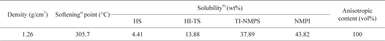
A 100 vol% mesophase pitch was used in this investigation. The properties are listed in Table 1.
[Table 1.] Material properties

Material properties
2.2. Design of spinning experiments
A laboratory-scale monofilament spinning apparatus was used in the melt spinning experiments. Each pitch sample was placed in a heating chamber and heated to a given spinning temperature. The molten pitch was extruded under pressurized nitrogen through a single-hole spinneret of 0.3 mm in diameter and 0.6 mm in length. The emerging extrudate was drawn by a take-up spool of 16 cm in diameter with varied winding speeds to form green fibers.
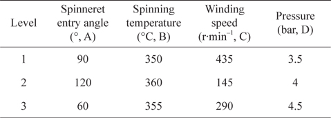
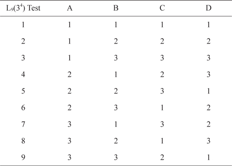
The design of the experiments was based on the method of Taguchi for the four factors at three levels. The four variables in the process were the spinning temperature, the nitrogen pressure, the entry angle of the spinnerets, and the spinning speed. Table 2 lists the factors studied and the assignment of the corresponding levels. A standard L9(34) orthogonal array was then employed to conduct the experiments (Table 3). The responses studied were the diameter, the crack angle, the preferred molecule orientation, and the tensile modulus of the obtained carbon fibers.
[Table 2.] Assignment of the levels to the factors

Assignment of the levels to the factors
[Table 3.] Orthogonal array L9(34) of Taguchi

Orthogonal array L9(34) of Taguchi
2.3. Stabilization and carbonization of mesophase pitch fibers
Mesophase pitch fibers from each fiber batch were cut into lengths of about 6 cm and were heated in air from room temperature to 160℃ at a heating rate of 5℃/min and then to 270℃ at 0.5℃/min. The oxidized fibers were obtained after stabilization at 270℃ for 80 min. The stabilized fibers were heated in an inert atmosphere to 1000℃ at 10℃/min, and further increased to 1400℃ at 5℃/min. The carbon fibers were obtained after carbonization for 30 min at 1400℃.
2.4. Characterization of carbon fibers
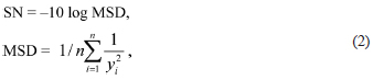
All fibers were observed under a polarized light optical microscope (OM; Jiangnan XP-221, Nanjing Jiangnan Novel Optics, Nanjing, China), from which the crack angles of the carbon fibers were determined. For each fiber batch, 40 fibers were randomly selected and used in the calculation. The cross-sectional textures of the carbon fibers were examined under a field emission scanning electron microscope (SEM; S4800, Hitachi, Tokyo, Japan). The diameters were determined for averaging 20 randomly selected fibers from each sample batch using FEI Phenom desktop SEM (Phenom, Eindhoven, the Netherlands). From the experimental results, the signal noise (S/N) ratio (the smaller the better) could be obtained as in [19] as:
SN = −10 log mean standard deviation (MSD),
where n is 20, and y is the experimental data of the diameter.
The preferred orientation along the fiber axis in the fiber bundles was determined by performing an azimuthal scan (−90° to 270°) at the fixed Bragg position (2θ=26°) of the (002) reflection, using a wide-angled X-ray diffractometer with an attachment for fiber samples (Rigaku Geigerflex; CuKa, 0.15406 nm, 40 kV, 250 mA). The degree of preferred orientation was measured and calculated from the half-width at half-maximum intensity of the (002) arc.
Single filaments were manually selected from a bundle of the testing fiber sample. For each set, fifteen filaments were mounted and tested, according to a procedure adopted from American Society for Testing and Materials (ASTM) C1557-03 [20], using a fiber tensile testing instrument XQ-1 made by Donghua Lipu Instrument. Briefly, each filament was mounted onto a paper card with cyanoacrylate adhesive, and care was taken to mount and position the fiber specimen linearly and vertically. The paper frame was cut before the test. The gauge length was fixed at 25 mm, and a crosshead speed of 1 mm/min was employed throughout the experiment. A non-contact laser micrometer [21] was introduced to directly measure the displacement of the flags attached to the fiber simultaneously during the test. All tests were conducted at room temperature in an air-conditioned laboratory. The tensile modulus was determined from the slope of the linear region of the stress-strain curve. Note that, to obtain the stress value, an equivalent diameter was used in area calculation based on the exemption of the crack open area. From the experimental results, the S/N ratio (the larger the better) could be obtained as in [19] as

where n is 15, and y is the experimental data of the tensile modulus.
3.1. OM and SEM observation of carbon fibers
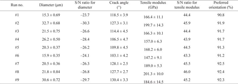
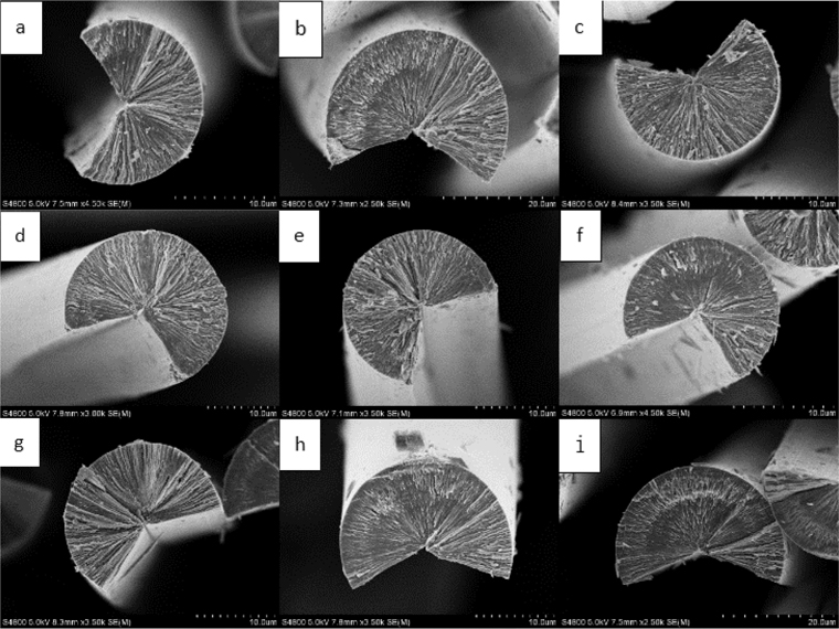
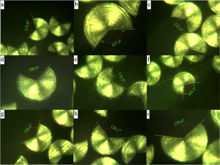
SEM photographs of the transverse sections of mesophase pitch carbon fibers from each run are presented in Fig. 1. For all nine runs, the carbon fibers show clearly defined radial texture in the transverse section with open cracks. Much finer texture can be observed in the outer zone than that in the core area. The bent feature [22] of the transition domains changes the contour under polarized light, as evidenced by the rings around the outer zone of the transverse section of the carbon fibers shown in Fig. 2. No significant difference can be observed on their textures. However, their diameters and crack angles vary from run to run as observed in the optical micrographs (Fig. 2). The measured values are listed in Table 4.
[Table 4.] Summary of the properties of carbon fibers from each run S/N, signal noise.

Summary of the properties of carbon fibers from each run S/N, signal noise.
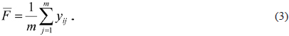
To investigate the role of the selected spinning conditions on the structure and properties of the obtained carbon fibers, the main effects of each factor have been calculated at each level. The mean effect of a defined factor at each level was obtained by adding the results of all trials conditions at the level selected and then dividing by the number of data points added:

The main effect value ΔF for each factor can be obtained by

where is the mean effect of the
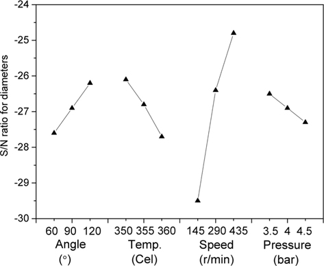
The mean effects of the selected spinning conditions on the S/N ratio for the diameter, crack angle, preferred molecule orientation, and S/N ratio for the tensile modulus are plotted in Figs. 3-6. The diameters of the carbon fibers were obtained in the range of 15.3–30.6 μm (Table 4). The coefficient of variation within each run was between 1.76% and 4.51%, indicating that stable spinning was achieved. In carbon fiber production, the fibers diameter should be as small as possible due to the “size effect” on the tensile strength [23,24] and the increased difficulty of achieving complete stabilization with thicker fibers [25]. Therefore, the S/N ratio was calculated based on the “smaller is better” quality methodology. As shown in Fig. 3, the most important variable affecting fiber diameter was the winding speed, followed by the spinning temperature and the entry angle. Increased pressure had a much smaller influence than other factors, but it still slightly increased the diameter.
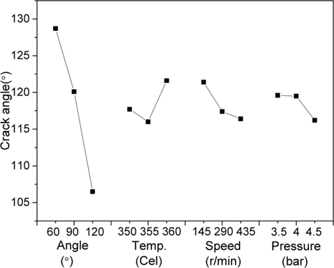
The open wedge crack is considered a common characteristic of MPCFs with radial texture [26]. Since the mesogen planes are aligned in the radial direction, the inter-plane bondings are fairly weak in the circumferential direction. During the post-heat treatment of as-spun fibers, hoop stress is generated due to the densification of the hexagonal carbon planes. Shrinkage along the circumferential direction thus induces cracks in the fiber texture [27]. As seen in Fig. 4, in the present study, the entry angle interestingly played the most important role in increasing the crack angle from 106° to 130° with its value decreased from 120° to 60°. Increased winding speed and pressure tended to decrease the crack angle, while the effect of temperature was non-monotonous. The crack angle decreased slightly as the temperature increased from 350℃ to 355℃, and a further 5℃ increment in temperature prompted crack development with a crack angle higher than that at 350℃.
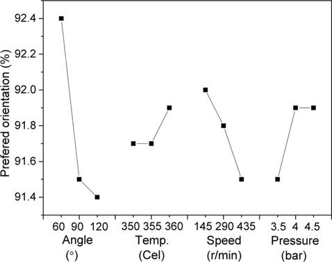
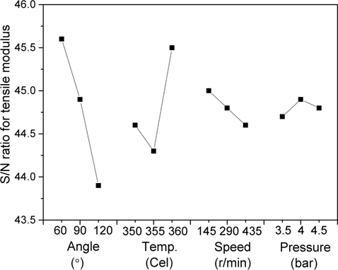
Like the crack angle, the spinneret entry angle had a significant effect; as the angle increased, the carbon fibers exhibited lower orientation (Fig. 5). Increased winding speed and decreased pressure also tended to lower the orientation. The least influential factor was the spinning temperature, the increased value of which tended to slightly increase the degree of preferred orientation. The S/N ratio on the tensile modulus results showed a similar trend as that of the preferred orientation (Fig. 6), except for the non-monotonous effect of spinning temperature, which was also seen in the crack angle results (Fig. 4). The tensile modulus of carbon fibers is directly related to the degree of the preferred basal plane orientation along the fiber axis [28]. Since the calculated equivalent area used in tensile modulus determination is influenced by the crack angle, it is not surprising to find that changes in the crack angle account for changes in the lattice-dependent tensile modulus. Here, the S/N ratio was calculated based on the principle of “the larger the better.”
3.3. Relationship between structural parameters and the properties of carbon fibers
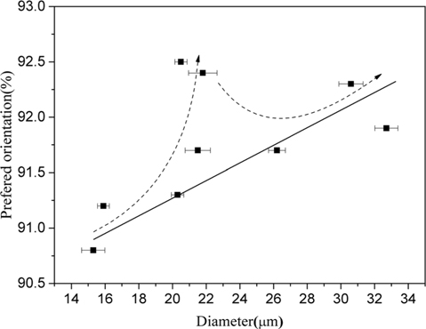
To further explore the structure-properties relationship of the obtained carbon fibers, the measured characteristics of all fiber batches were sorted and analyzed as reported in this section. Fig. 7 shows the degree of preferred orientation of MPCFs as a function of the average diameter. The main trend is consistent with the results from Hamada et al.’s [10] and Lu et al.’s [25] studies that as the diameter increases, the preferred orientation of carbon fibers improves significantly. A sharp increase in preferred orientation was observed at 20 to 22 μm (denoted by dash line in Fig. 7), followed by a decrease and thereafter a gradual increase in the preferred orientation with diameter. According to the model proposed by Difendorf and Kurtz [29], the degree of preferred orientation of mesophase molecules along the fiber axis results from the competitive effects of the relaxation and introduction of the disorder induced by elongation during spinning. It is suggested that a thermodynamic disorder state is retained at high temperature. As the molten mesophase pitch is extruded from the spinneret, being stretched into a thinner fiber, it is more likely that the supercooling effect enables a disordered state to be retained rather than relaxed by slow cooling in thicker filament formation. Carbon fibers with diameters of 20–22 μm may receive an optimum balance from the cooling speed and elongational stretching force to exhibit better molecule orientation than those produced under other conditions.
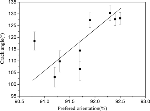
The crack angle has a nearly linear dependence on the degree of preferred orientation, except for the one with the lowest degree of preferred orientation that deviates from linearity (Fig. 8). As mentioned above, cracks develop due to the circumferential shrinkage of mesogen planes. Cracks were found to be widely broadened with heat treatment from carbonization to graphitization [27], where the preferred orientation was largely improved [30]. The results obtained here further prove that improved preferred orientation prompts crack development.
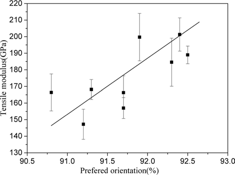
In this study, although only spinning conditions were varied while the carbonization conditions were kept constant, carbon fibers were still successfully obtained with various degrees of preferred orientation. This result suggests that the melt spinning process plays a very important role in structural development during carbon fiber formation. Small differences in molecule orientation influence the macrostructural arrangement, such as crack formation and other properties, such as the tensile modulus (Fig. 9). The tensile modulus is a lattice-dependent property that is strongly affected by the basal plane orientation along the fiber axis. The theoretical tensile modulus of single-crystal graphite is 1060 GPa. However, the highest value that the current carbon fibers could obtain was far below the theoretical one. It is believed that by increasing the orientation, the full benefits of the C-C bond can be exploited, so as to increase the tensile modulus, as demonstrated in Fig. 9.
The aim of the present work was to explore the effects of spinning conditions on the structure of carbon fibers. Taguchi’s method was used to identify the relative importance among the factors studied. The spinning of mesophase pitch has never been easy due to its highly temperature-dependent viscosity and the brittle nature of as-spun mesophase pitch fibers [2]. The selection of variable values to fill an orthogonal array has to meet the following minimum criteria.
1) Spinning must continue for least 15 min to present a stable output from the input of the designated processing conditions.
2) The diameter of the pitch fibers obtained under all the designated processing conditions has to be kept under 35 μm to ensure that the pitch fibers are fully stabilized.
Under the above described circumstances, there is a rather narrow processing window for melt spinning, as seen from the levels of spinning temperature and pressure. However, a convincing trend can still be spotted based on the experimental results, and it has a strong implication regarding the general behavior the mesophase pitch may exhibit.
The effects of spinning conditions on diameter (Fig. 3) can be predicted from the mass equation for spinning [4]:

where Q is the flow rate, ρ is the density,
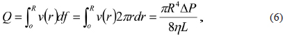
where R is the capillary radius, L is the capillary length,
Regarding the effect of the spinneret entry angle during the fiber spinning of mesophase pitch, very few works can be found in the literature so far. Fleurot [33] experimentally observed and simulated the flow of molten mesophase within a spinneret capillary with varied entry angle. He reported that the size of vortex in the corner of the capillary counterbore was reduced with smaller entry angle. However, no exploration on the structure or properties of carbon fibers had been conducted. Nothwang et al. [34] mentioned that the variation of spinneret entry angle had an effect on the properties of carbon fibers produced. However, no open data can be found. In the present work, the spinneret entry angle was demonstrated to have a significant influence on fibers characteristics. Considering a converging flow from a chamber to a capillary with much smaller diameter, extra pressure drop would be generated to contribute to the total pressure drop in the capillary, which can be expressed as

where ΔPcap is the pressure drop over the length of the capillary where the flow is fully developed, and ΔPend is the extra pressure drop including entry and exit pressure drop. Since exit pressure drop is relatively small, only entry pressure drop is considered here. The converging flow exhibits complex patterns where shear and extensional regions co-exist. The shear dominated flow is near the walls, and along the centerline it is purely extensional. Consequently, a number of elastic deformation energies are consumed or stored in the melt, leading to obvious entry pressure drop. The entry pressure drop is influenced by the spinning conditions, such as spinning temperature, shear rate, and channel geometry, such as the shape of cross section, diameter, and entry angle. In the investigation of the effect of entry angle on entry pressure drop for polypropylene [35], Mitsoulis and Hatzikiriakos found experimentally and numerically that the entry pressure drop decreases for the same apparent shear rate with an increasing contraction angle from 10° to about 45°, and consequent slight increases from 45° to contraction angles of 150°. In a smaller angle converging flow, shear flow dominates, while elongation becomes important at higher contraction angles (greater than 45°). In Liang’s study on an natural rubber/styrene butadiene rubber compound [36], there was a natural converging angle of 75°, at which the total pressure drop reached the minimum value. Above the entry angle of 75°, the pressure drop increased as a consequence. This indicates that the optimal die angle for achieving minimum entry pressure drop is different for various molecular configurations and various compositions of sample materials. In the present study, as shown in Fig. 3, an increased tapering angle tends to reduce the diameter. According to eq 7, at a given applied extrusion pressure ΔP, the increased ΔPend tends to reduce the effective ΔPcap; hence, the flow rate is reduced as discussed above. Thus, we suggest that the optimal die angle for achieving the lowest entry pressure is below 60° or between 60° to 90°. Further work on Bagley correction results are needed to validate this speculation.
As analyzed in the above section, MPCF with increased diameter generally possesses higher molecule orientation along the fiber axis. The crack angle and tensile modulus are directly related to the preferred orientation. Therefore, the spinning conditions affecting the diameter generally have a similar impact on the crack angle (Fig. 4), preferred orientation (Fig. 5), and tensile modulus (Fig. 6). However, the most significant factor affecting the diameter and other characteristics vary, as revealed by the Taguchi experimental results. In affecting the crack angle, the preferred orientation, and the tensile modulus of the obtained carbon fibers, the entry angle was found to be the most important factor. Thus, the obtained preferred orientation is not only influenced by the thermodynamic mechanism during the stretching process after extrusion, but more importantly, it is a result of the flow-induced structural development in entry converging flow. As a nematic liquid crystalline material comprising discotic-like molecules, mesophase pitch possesses a primary feature that it is much easier to orient than ordinary polymers. This is due to the co-operative nature of a nematic phase [37], in which molecules slide past each other more readily, and their localized domains are already mutually oriented in a roughly parallel fashion. The orientation developed in the converging section of the die involves both shear and extensional flow. Shear flow is known to destroy and deform the polydomain microstructure of mesophase pitch [38,39], resulting in a reduction in the size of the domain to a finer texture [40]. The stretching applied by the extensional flow may consolidate and orient it [41]. As discussed above, the flow mechanism is dependent on the angle of convergence, the change of which influences the relative contribution of shear and extensional flow. It is generally recognized that at a small angle, the shear flow dominates, and elongation becomes important at higher contraction angles [35]. In the present study, the preferred orientation and the resulting crack angle and tensile modulus are higher at a smaller entry angle. This is consistent with Fleurot’s results [33], in which a profiled entry spinneret was more efficient than a flat entry spinneret in retaining a radial structure. A similar interpretation can be obtained from results that showed that as the L/D of a capillary spinneret increased, where the effect of shear flow was enhanced, the texture of the carbon fibers produced by Matsumoto [3] evolved from onion-like to radial, or for the radial-texture carbon fibers obtained by Yoon et al. [27], the open crack angle increased. In Kundu and Ogale’s study [42] on the flow-induced microstructural evolution of mesophase pitch in both the counterbore and capillary sections, enhanced orientation in the capillary was observed with a high shear rate from the counterbore with a low shear rate, and this was attributed to the high shear stress experienced in the capillary. Jian et al. [43] experimentally determined the surface anchoring states of mesophase pitches on free surfaces and solid substrates, and they reported that edge-on anchoring is the most common state for various materials, including the stainless steel used as the capillary wall material in this study. Such edge-on orientation of discotic mesogens would preferentially provide radial orientation of layer planes in the capillary.
It should be note that the spinning temperature, normally considered as the most important variable affecting fiber characteristics, was less influential than spinneret entry angle in achieving an improved preferred orientation. This may be due to the relatively narrow span of the designated value or the raw materials used. However, it implies that during the production of carbon fiber using the current setting, the optimization of the spinneret design might be more effective than manipulating the spinning temperature. This finding is of particular interest for directing the further optimization of carbon fiber production.
Numerous studies have been conducted on specifying the effect of spinning conditions on the carbon fibers produced. However, their relative importance had not been examined in detail. The application of Taguchi’s method in melt spinning experiments on mesophase pitch was proven to be effective in two ways. First, the effects of processing variables (four factors) on the carbon fibers were thoroughly explored over only nine experiments. Second, the relative importance of the variables has been identified, providing very useful information for future fiber production if optimization is to be conducted. Smaller entry angle, higher spinning temperature, reduced winding speed and increased extrusion pressure were found to produce thicker carbon fibers with improved preferred orientation. Spinning speed was found to be the most important factor affecting the diameter, followed by entry angle and spinning temperature. The effect of entry angle was found to be much more important than other factors in defining the preferred orientation. This result indicates that both the flow-induced orientation within the profiled capillary and the thermodynamic mechanism during the stretching process influence the preferred molecule orientation of carbon fibers, while the former one was considered to be more important. The crack angle and tensile modulus were dependent on the preferred orientation; thus, similar trends were observed in the results.