


There has been a pronounced increase in the use of advanced composite materials in the fabrication of structural elements, in the aerospace industry, in sporting goods, and in the automotive industry [1-4]. The main advantage of using composite materials in structural applications lies in their highly attractive strength/weight and stiffness/weight ratios. However, their toughness is important, especially when considering design criteria based on the energy absorption capability of the composite. In the technical literature, a large body of research seeking to improve the fracture toughness of epoxy resins can be found. These efforts include the use of high toughness materials such as elastomers and thermoplastic polymers. Also, the use of hybrid-fiber reinforcements such as mixtures of Kevlar, glass and carbon fibers has been explored. A comprehensive study regarding the improvement of the fracture toughness of epoxy resins was reported by Kim and Mai [5]. Escalante-Solís [6] studied the effect of the method of dispersion of polysulfone (PSF) in an epoxy resin on its Izod impact strength and found that using an ultrasonic probe improved the dispersion of the PSF domains and increased the Izod impact strength by approximately 30%. Brantseva et al. [7-9] studied the processes during matrix/glass fiber interface formation, adhesion of the epoxy-polysulfone matrices to glass fibers and the properties of cured blends and their structures in the polymer/fiber interphase, in a set of three papers. They found that the structure of the cured epoxy-polysulfone blends depended on the modifier concentration and that the modification of the resin by polysulfone did not change the kinetics of fiber wetting by the blends. They also found that the incorporation of PSF into epoxy resin changed its adhesion to glass fibers. Finally, they determined that the incorporation of PSF in resin epoxy did not lead to appreciable changes in the linear thermal expansion coefficients and the glass transitions temperatures of the cured blends and that it did not result in a significant increase in the internal stress in the system.
Yun et al. [10] used a polysulfone film to improve the fracture toughness of a carbon fiber/epoxy composite and showed that this property increased 2.7 times as compared to the unmodified composite. Solodilov and Gorbatkina [11] studied an epoxy resin modified with a polysulfone or a PEF-3a epoxyurethane oligomer. Triethanolaminotitanate or diaminodiphenilsulphone was used as a hardener. This modification did not improve the mechanical properties of the glass fiber reinforced plastics (GFRP) in quasi-static loading; however, the shear strength of epoxy-polysulphone GFRPs with 20 wt%, in a low-speed impact loading, increased by 20%–25%. Guduri and Luyt [12], studied an epoxy, prepared through aminomethyl 3,5,5-trimethylcyclohexylamine hardening of diglycidylether of bisphenol A (DGEBA) prepolymer, toughened with polycarbonate (PC) in different proportions, and reinforced with carbon fiber. They also found that the tensile and interlaminar shear properties of the epoxy-carbon fiber composites could be greatly improved by modification of the epoxy with the PC. The tensile properties of the blend matrix increased with the PC content up to 10%, beyond which it decreased.
The role of fiber-matrix adhesion on the fracture and delamination behavior of epoxy resin carbon fiber composites has been widely studied by Madhukar and Drzal [13]. They found that when the interfacial shear strength (IFSS) is low, the mode I fracture toughness (GIC) of the composite could not be determined from the double cantilever beam (DCB) test because of sudden failure of the specimens upon load application. However, when the IFSS was increased, the GIC also increased. The experimental results demonstrated that there is a strong dependency of mode II fracture toughness (GIIC) on fiber-matrix adhesion. Increased fiber-matrix adhesion in one group of composites significantly improved the GIIC, but the presence of a brittle interphase around the graphite fibers in another group of composites tended to cancel part of the improvement resulting from increased adhesion. Based on the major failure modes occurring during the mode I and mode II loading conditions, a causal linkage between fiber-matrix adhesion and the interlaminar fracture behavior of graphite/epoxy composites was established.
Most of these studies have centered on either the physical, chemical and/or the effective mechanical properties of the composites resulting from the matrix modification; that is, on the effect of the new polymer-blend matrix or the effect of the modifications of the surface fiber to control the fiber-matrix interphase interactions and the IFSS, and the resulting effective mechanical properties of the composites. Very little attention has been paid to the extent of the contribution of the matrix-modification or the contribution of the improvement of the fiber-matrix IFSS or the combined effect of both on the mechanical properties, and specifically on the fracture toughness, of a carbon fiber reinforced modified-epoxy matrix. Thus, the main objective of this work is to study the effect of the interactions (synergy) between the epoxy matrix modification with the inclusion of a thermoplastic polymer, namely polysulfone, on two levels of carbon fiber-matrix adhesion, and their contribution to the mode I fracture toughness of the composite [14,15].
High strength, intermediate modulus carbon fibers (CF) IM7 from Hexcel Corporation (Salt Lake City, UT, USA) with 12,000 filaments in the tow was used. The epoxy resin was DGEBA, Epon828, from Shell Company, Mexico. Metaphenylenediamine (mPDA), from Sigma-Aldrich Chemical, Mexico, was used as a curing agent. The carbon fibers were treated with 3-glycidoxypropyl trimethoxysilane (Z-6040; Dow Corning Corp., Mexico City, Mexico). The thermoplastic polymer used was PSF Udel P-1700 (Solvay Advanced Polymers Co., Orange, TX, USA).
For the removal of the commercial sizing, the fibers were initially immersed and refluxed in methyl-ethyl ketone in a kettle reactor for 12 h. Then, they were washed with acetone and distilled water and then dried in an oven at 120℃ for 24 h. The oxidation of the CF was carried out in a Kettle reactor refluxing nitric acid (70% purity) for 6 h. Afterwards, the fibers were refluxed for 2 h with distilled water to remove any traces of the acid. Finally, they were dried in an oven at 120℃ for 2 h. For the silane surface treatment, the fibers were immersed in a solution of 0.1% (w/w) silane and (50% v/v) distilled water and methanol, with a pH of 4.5, for 1 h. Afterwards, they were dried in an oven at 120℃ for 2 h [16].
2.3. Thermoplastic modified epoxy resin
The modified epoxy resin was prepared as follows: the desired amount of polysulfone (8.75% w/w) was dissolved in dichloromethane (CH2Cl2), mixed with the epoxy resin and sonicated for 10 min. Next, the mixture was gradually heated to a temperature of 110℃ and kept constant until all the dichloromethane was volatilized. Afterwards the mixture was cooled to 75℃ under vacuum. The mPDA catalyst (14.5% w/w) to cure the resin was added stirring continuously using a magnet and allowed to cure for 2 h at 75℃ and then, the temperature was increased to 125℃ and kept for 2 h. Next, the oven was turned off and the resin was allowed to cool down to room temperature.
A two-level full factorial design 22 with two replications was employed to investigate the effects of the carbon fiber surface treatment and the epoxy resin modification on the tensile mechanical properties and the fracture energy GIC of the composites. A statistical analysis of the data was performed using commercial software, Design Expert 7 (Stat-Ease Inc., Minneapolis, MN, USA). The analysis of variance (ANOVA) provided a study of the variation present in the results of the experiments carried out, and the test of statistical significance,
The labels of the two independent variables studied and the nomenclature used are indicated in Table 1 as follows: F(No) indicates that the fiber surface was not treated and F(Mo) indicates that the fiber surface was treated with the silane coupling agent. In the case of the epoxy matrix, R(No) indicates that it was not modified and R(Mo) that the epoxy matrix was modified with 8.75% w/w of the thermoplastic PSF.
[Table 1.] Nomenclature used to label the different epoxy-matrix or carbon-fiber modification
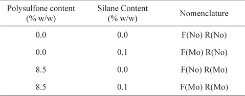
Nomenclature used to label the different epoxy-matrix or carbon-fiber modification
Prepregs of carbon fibers and epoxy resin were made using an in-house made prepregging system. The prepregs were cut and layered to form 20 × 20 cm laminae. The laminates were made by stacking up eight laminae, and then they were cured in a flat mold in a vacuum bag, following the same procedure recommended for the resin, i.e., 2 h at 75℃ followed by a post cure at 125° for 2 h. Then, it was allowed to cool down to room temperature before removing it from the mold [18]. The final fiber volume fraction in the laminate was determined according to recommendations given by the American Society for Testing and Materials (ASTM) D3171-49 standard [19].
2.6. Mechanical characterization
2.6.1. Tensile properties characterization
For the tensile tests, [0]8 laminates were used, and the specimens’ dimensions were 15 mm wide, 1.8 mm thick, and 250 mm long. Tabs were bonded to the specimens according to the recommendations in the ASTM D3039 standard [20]. These tabs were approximately 56 mm long and 1.5 mm thick and were attached using an epoxy resin. The final gage length of each specimen was 148 mm.
The tensile testing was performed using a Shimadzu universal testing machine (model AG-I) equipped with a 100 kN load cell and a crosshead speed of 5 mm/min, at ambient temperature (25℃). At least five samples were tested after conditioning at room temperature (25℃) for at least 2 d prior to testing.
2.6.2. Fracture toughness
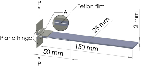
For the mode I interlaminar fracture toughness (GIC) tests, the [0]8 laminates were used and a non-adherent film (Teflon film), 7.5 µm thick, was inserted in the mid-plane of one edge perpendicular to the fibers direction, to introduce an artificial mid-plane crack initiator. The specimen dimensions were 2 mm thick, 25 mm wide and 150 mm long. A piano hinge was bonded to the free end using epoxy resin.
The initial crack was 50 mm, as shown in Fig. 1. The mode I interlaminar fracture toughness was measured using a Shimadzu universal testing machine (model AG-I) equipped with a 5 kN load cell, using the standard DCB specimen, at a rate of 2 mm/min, according to the ASTM D5528-94 standard [21]. The specimen was pulled under displacement control mode until the crack grew approximately 10 mm. The machine was then stopped and the crack was allowed to come to a point of arrest. The new crack lengths were observed on the specimen edge with the help of a layer of white paint and equally spaced marks, and recorded using a video camera. The specimen was loaded again and the same step was repeated an additional 5 times to obtain a relationship between 1) compliance and crack length and 2) critical load and crack length. The load–displacement
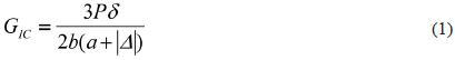
2.6.2.1. Data reduction scheme
In the DCB test, the loads,

where
2.6.3. Scanning electron microscope
The micro-features of the failure surface of the specimens as well as the possible influence of the presence of the PSF were observed using a scanning electron microscope (SEM; JSM-6360 LV; JEOL Peabody, MA, USA). The samples were coated with gold using a sputter coater.
The tensile mechanical properties of the different composite laminates and their fiber content are shown in Table 2. It can be seen that the fiber volume fraction is practically the same for all composites, suggesting that the staking sequence and the curing parameters of the composites were similar.
[Table 2.] Mechanical tension properties of composites
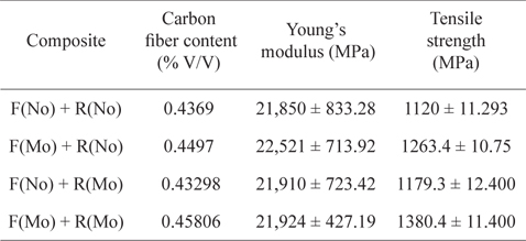
Mechanical tension properties of composites
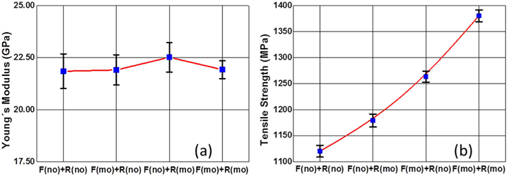
In order to better appreciate the effect of the different treatments on the composites’ mechanical properties, they are shown in Fig. 3, where it can be observed that neither the fiber treatments nor the PSF inclusion modified the composite elastic modulus. This behavior is in agreement with the fact that the elastic modulus is dependent on the fiber content rather than the fiber-matrix adhesion [22].
On the other hand, it is evident in Fig. 3b that the magnitude of the tensile strength (TS) depends on both the fiber and matrix treatments. In this figure, it can be seen that the fiber surface modification alone increases the TS by almost 13% and the matrix modification alone only a 5%. However, a 23% increment in the TS can be observed when comparing the fabricated composites, when both the fiber and the matrix were treated (F(Mo) + R(Mo)), with those made with the untreated ones (F(No) + R(No)). These findings suggest a synergy between both treatments.
3.1.1. ANOVA of the tensile mechanical properties
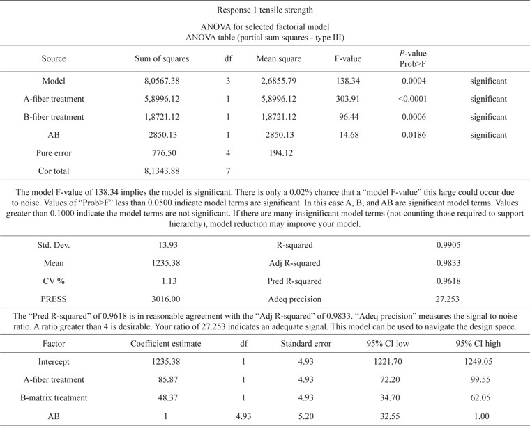
ANOVA of the TS results is shown in Table 3, where it can be seen that both modifications are statistically significant, even their interaction.
[Table 3.] ANOVA results for the tensile strength

ANOVA results for the tensile strength
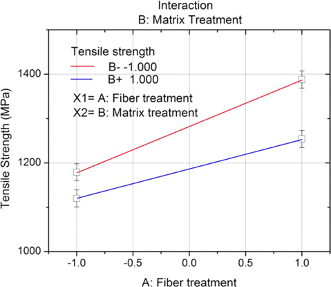
The statistical significance of the interaction term suggests that there is a synergy between the fiber surface treatment and the thermoplastic matrix modification. This combined effect of the treatments can be observed in Fig. 4, where it is evident that the increment of the TS due the fiber surface treatment depends on the nature of the epoxy matrix. That is, for the pristine epoxy resin, the TS increased 13%, whereas, using the polysulfone-modified epoxy raised it 17%.
On the other hand, the effect of incorporating polysulfone in the epoxy matrix on the TS also depends on the fiber surface treatment. For untreated carbon fiber, the TS increased 5%, and 10% when using the silane treated carbon fibers. It should be noted that the silane treatment made a large contribution to the TS compared with the incorporation of polysulfone.
This behavior can be attributed to the formation of covalent bonding between the silane treated carbon fiber and the epoxy resin, which enhances the interphase strength [23]. On the other hand, the incorporation of the polysulfone has two main effects: it decreases the surface energy and raises the viscosity of the blend. The former promotes better wetting of the fiber, whereas the latter slows the motion of the chains and retards the wetting. The net effect is a small increase in the mechanical component of adhesion by interlocking [7].
3.2. Mode I interlaminar fracture toughness
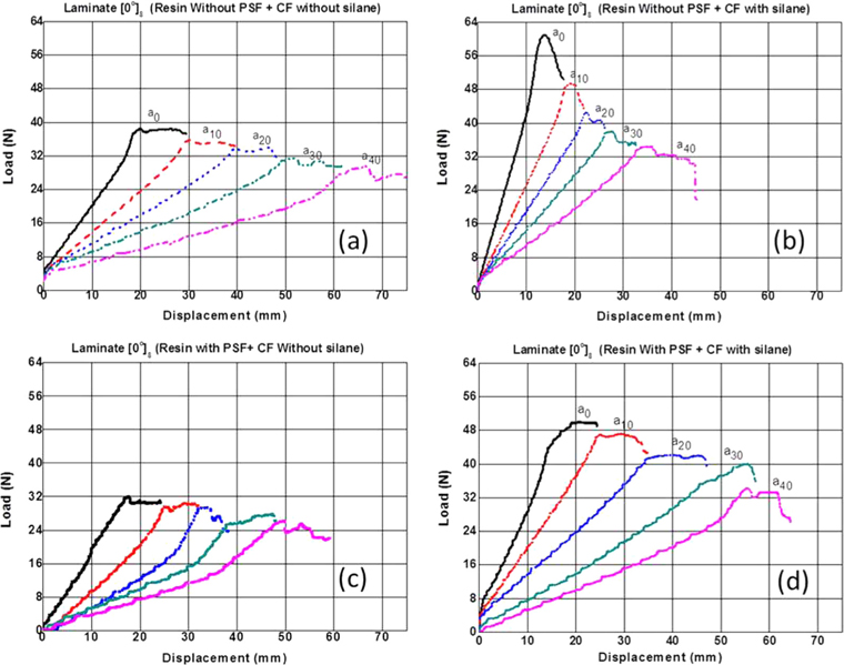
Typical load-extension and crack growth curves obtained from the DCB tests specimens of carbon fiber reinforced plastics (CFRP) composites are shown in Fig. 5, where it is evident that both the fiber surface treatment, as well as the inclusion of the thermoplastic polymer in the epoxy resin, have an effect on their behavior. Fig. 5a shows the load-displacement for the untreated fiber (F(No)) and the pristine epoxy matrix (R(No)).
The effect of the silane treatment on the crack growth curves is shown in Fig. 5b, where it can be seen that both the load and the slope of the curve increase as a result of better fiber-matrix adhesion [24]. The effect of the PSF inclusion on the epoxy resin on the crack growth curve is shown in Fig. 5c, and corresponds to the F(No) + R(Mo) composites. It can be seen that the slope of the curves are greater than the ones in Fig. 5a, suggesting there is better wetting of the carbon fibers, since the polysulfone-epoxy matrix has a lower surface energy than the pristine epoxy matrix [7].
Compared with Fig. 5a, the composite with both the silane fiber-surface treatment and the matrix modification shows a greater load and rigidity, resulting from the stronger fiber-matrix adhesion. Also, the role played by the matrix in the energy dissipation process is evident in Fig. 5d.
It should be pointed out that in this composite material, two different mechanisms for energy dissipation coexist. On one hand, the strong covalent bonds between the fiber and matrix resulting from the presence of the silane compound, efficiently increases the load-bearing capacity of the composite. On the other hand, the PSF regions in the matrix play a very important role in energy dissipation during crack growth or delamination, probably by crack growth arrest and/or thermoplastic material plastic deformation [9].
The mode
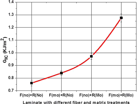
The fracture energy required to propagate a crack, GIC, is shown as a function of matrix and fiber treatments in Fig. 6, where it can be observed that GIC increases with both the fiber and matrix treatments (F(Mo)+R(Mo)) by about 70%, compared with (F(No) + R(No)). Madhukar and Drzal [13] demonstrated that the interlaminar fracture toughness of the composite and failure modes strongly depends on the matrix adhesion.
3.2.1. Analysis of ANOVA of the interlaminar fracture toughness
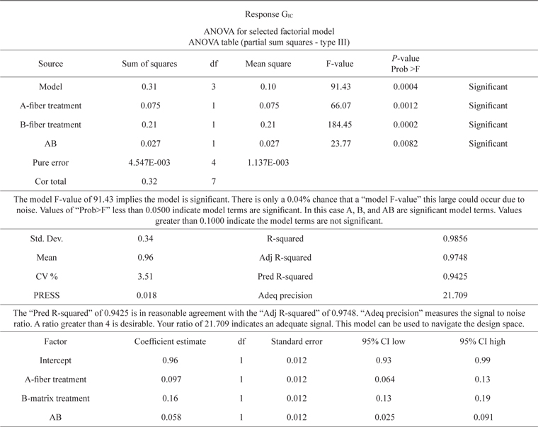
ANOVA of the fracture energy required to propagate the crack GIC results are shown in Table 4, where it can be seen that both the thermoplastic matrix modification and the carbon fiber surface treatment are statistically significant as well as their interaction.
[Table 4.] ANOVA results for fracture energy GIC

ANOVA results for fracture energy GIC
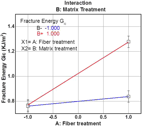
The importance of the interaction between treatments can be observed in Fig. 7, where it is evident that there is a combined effect (synergy) between both modifications, since the increase in GIC due to the silane surface treatment depends on the nature of the epoxy matrix. For example, in the presence of pristine epoxy, the GIC increased 15%, whereas when using the polysulfone-modified epoxy matrix, it increased by 32%.
Moreover, the effect of the incorporation of polysulfone on the epoxy matrix in GIC also depends on the fiber surface treatment. For the untreated carbon fiber, the GIC increased 30%, however, it increased by 50% when using silane treated carbon fibers with the polysulfone-modified epoxy matrix.
It should be noted that incorporating the thermoplastic polysulfone in the epoxy resin makes a large contribution to the GIC, compared with the silane fiber treatment. This behavior could be attributed to the presence of inclusions which do not allow easy propagation of cracks through the interface. The role of the inclusion may be to change the direction of propagation of the crack. In this case, since more and smaller inclusions of PSF are present in the composite, more routes of possible energy dissipation will be created.
Liu and Nauman [26] pointed out that the presence of inclusions acts as a yield initiator as well as a crack arrestor. However, they also found that the adhesion between particle and matrix becomes more important as the stiffness of the inclusion increases.
Johnsen et al. [27] in their study of thermoplastic/epoxy blends found that the nature of the micro-mechanisms responsible for the increase in toughness of the blends could be identified as follows: for the reaction-induced phase-separation blends, 1) debonding of the PSF particles, was followed by 2) plastic void growth of the epoxy matrix. They were the major toughening micro-mechanisms, and the increase in toughness due to such micro-mechanisms was successfully predicted theoretically using an analytical model.
In the case of the crystallization-induced phase-separation blends, the increase in the value of GIC resulted from 1) crack deflection and 2) micro-cracking and crack bifurcation. Furthermore, for the material in which the fiber and matrix were both modified.
Fig. 7 shows an increase of 70% with respect to F(NO)+R(NO). This increase is attributed to the improved fiber surface, and the inclusion of the PSF. When the carbon fiber is surface modified crack propagation occurs through the matrix, but in turn, to find the presence of polysulfone, the crack requires more energy to propagate, increasing this path (Fig. 8).
It should be mentioned that between the PSF and the epoxy resin, which are immiscible, one cannot exclude the existence of interfacial mechanical mechanisms, causing plastic deformation during the crack propagation. Finally, we should comment that when the increases are analyzed separately, they show a linear trend. But from the results of the composite, when both fiber and matrix are modified, the increase is not a linear trend and there seems to be a collaboration of both, the PSF inclusion and the fiber-matrix adhesion, in inhibiting crack propagation, thus producing a synergistic result in the improvement of the toughness [11,28-31].
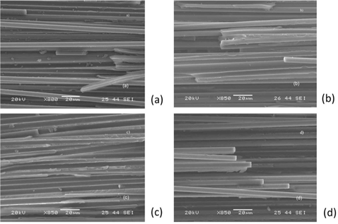
3.3. SEM characterization of failure surfaces
Fig. 8 shows photomicrographs of the failure surface for the laminates, corresponding to two levels of fiber-matrix adhesion. Both Fig. 8a and c, for the non-treated fibers, show the typical appearance of major pull-out failure as well as clean fibersurfaces, thus indicating that failure was catastrophic. In Fig. 8a, it is evident that the fiber and the pure matrix bonding is very poor, and that the pure epoxy is very brittle in nature, and the composite specimen easily fails when loaded.
Mechanical interlocking provides a moderate interface bonding, and even though other effects are higher [32], these observations suggest the need for surface modification of the carbon fiber, probably by using different coupling agents, heat and plasma treatments.
On the other hand, Fig. 8b and d show a considerable improvement in the composite surface toughness. This increase may be attributed to fiber-matrix adhesion, that is, to the chemical covalent bonds between the fiber surface modified-fiber and the epoxy matrix. It is also evident that the presence of the polysulfone in the matrix makes no significant contribution to the fiber-matrix adhesion [33].
Two different mechanisms of fracture energy GIC improvement were noticed. First, the fiber-matrix adhesion plays a very important role in the improvement of the fracture toughness. Also, the failure mode changes, and the catastrophic failure observed for the untreated fiber composites are no longer observed for the silane treated fiber. The inclusion of polysulfone in the matrix also affects the delamination properties of the composite material, and results in an increase in the fracture energy, GIC. However, when both the fiber surface is treated with a coupling agent to increase fiber-matrix adhesion, and the matrix is modified with the inclusion of a thermoplastic toughening polymer, a synergistic effect on the tensile mechanical properties, as well as on the fracture energy GIC, seems to exist.


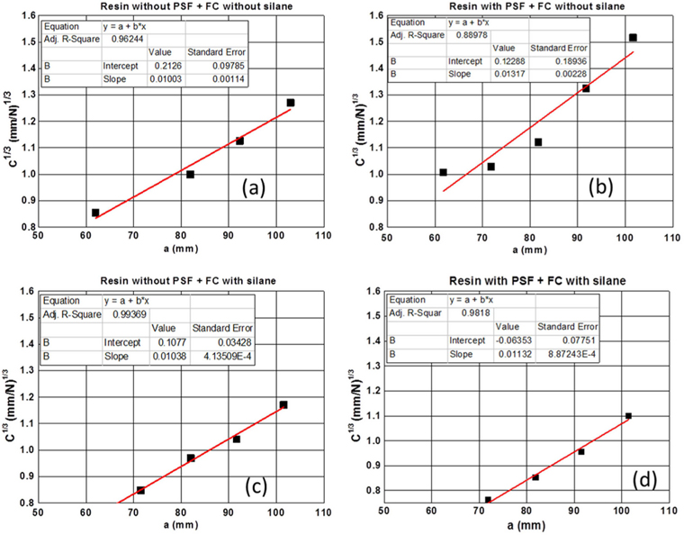
![Compliance calibration curves of double cantilever beam specimens made from carbon fiber reinforced plastics (CFRP) composites modified with polysulfone (PSF) resin and carbon fiber surface modified with silane. (a) (Resin without PSF + carbon fibers [CF] without silane), (b) (resin with PSF + CF without silane), (c) (resin without PSF + CF with silane), (d) (resin with PSF + CF with silane).](http://oak.go.kr/repository/journal/21258/HGTSB6_2016_v19n1_47_f002.jpg)


![Schematic load-displacement records during crack growth for a double cantilever beam test. (a) Laminate [0°]8 (resin without polysulfone [PSF] + carbon fibers [CF] without silane), (b) laminate [0°]8 (resin without PSF + CF with silane), (c) laminate [0°]8 (resin with PSF + CF without silane), (d) laminate [0°]8 (resin with PSF + CF with silane).](http://oak.go.kr/repository/journal/21258/HGTSB6_2016_v19n1_47_f005.jpg)