


As the refractive index is very close to unity for all materials at x-ray wavelengths [1], an x-ray beam cannot be focused by refraction. The use of diffractive elements to realize x-ray focusing is an alternative method. Fresnel zone plates (FZPs) have been the most widely used diffractive elements for hard-x-ray focusing. Applications include synchrotrons, free-electron lasers, and other laboratory sources. FZPs can achieve very high spatial resolution [2]. Typically, an amplitude FZP consists of a series of alternating transparent and opaque concentric rings (zones) of prescribed radii [3]. A phase-shifting FZP has concentric rings causing alternating phase delay. Because it is efficient for the focusing of hard x-rays (photon energies above 8 keV) [4], a Fresnel zone plate with submicrometer dimensions has been used for purposes such as x-ray telescopes, micro-fluorescence, microimaging, microspectroscopy, and microdiffraction. In these applications the focusing of hard-x-ray beams is an important requirement for each experimental technique.
Spatial resolution and absolute focusing efficiency are two important parameters of an FZP. The diffraction limit of an FZP is associated with the smallest, outermost zone width. A nanolithography process with sufficient resolution has to be applied during fabrication. For an ideal FZP, analytical formulas have been developed to calculate the focusing efficiency, focal spot, and focal depth for a given incident wavelength. The focusing efficiency for an ideal amplitude FZP is about 10%, and about 40% for an ideal phase FZP [5]. The radius of the focal spot is
This paper presents numerical simulations to systematically study the influence of nonideal factors on the focusing properties of an FZP. The paper is arranged as follows: Section II introduces the theoretical methods of the numerical calculations; Section III discusses the influences of several nonideal factors on focusing properties; and Section IV presents the conclusions.
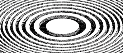
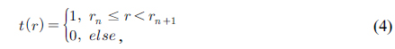
The structure of a Fresnel zone plate, consisting of alternating transparent and opaque zones, is shown in Fig. 1. When a plane wave with a wavelength of
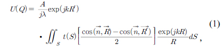
where

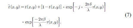
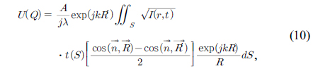
Using Eqs. (1) and (2), the focusing properties of the zone plate in the focusing region can be numerically calculated, as long as the transmission function of the FZP is determined. The focal-spot radius, focusing efficiency, and other information can also be obtained by simulations.
In the application of FZPs, there are often some nonideal factors, which lead to a great difference between the actual focusing properties and the ideal situation. For example, due to the strong penetration of hard x-rays, the influence of material absorption and phase shift caused by thickness is worth considering. The actual manufacturing errors in an FZP, such as step sidewall tilt, may also affect the focusing properties. To realize self-support of the zone plate’s structure, the presence of intentionally added metal struts is not negligible. Since FZPs have been widely used in the focusing of ultrashort x-ray pulses, such as synchrotron radiation and free-electron lasers, the effect of the FZP’s structure on the pulse duration of the focal spot is a valuable research issue.
3.1. The Effects of Film Thickness
The structure of an FZP for x-ray-focusing applications is shown in Fig. 2. The white areas are the structures of the opaque concentric rings, generally made using high-
For hard x-rays, the refractive index of almost all materials tends to unity, so the refractive index can be expressed as
where
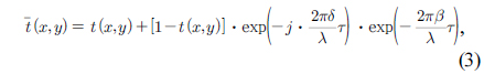
In Eq. (3),
where is the radius of zone
According to the classical theory of x-ray FZPs, the highest focusing efficiency that can be reached is approximately 40% when and are satisfied. However, in the actual design process, the two conditions are very difficult to satisfy simultaneously. Generally the phase matching of the thickness of an x-ray FZP is the first criterion in the design process.
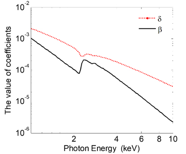
Figure 3 shows the complex refractive index coefficients 𝛿 and
The parameters of the numerical simulations are shown in Table 1. It should be noted that this paper only takes the parameters in Table 1 for example, and FZPs with other parameters can also be calculated by the methods of numerical simulation proposed in this paper, which can be used to guide the design and application of FZPs.
[TABLE 1.] The parameters of the FZP for numerical simulations
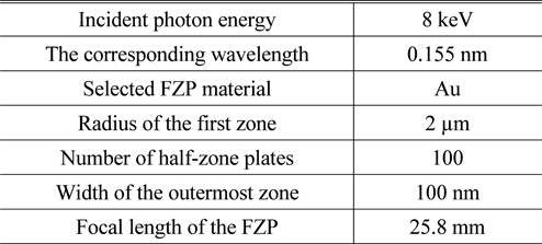
The parameters of the FZP for numerical simulations
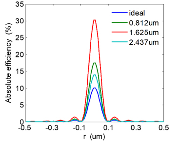
As shown in Fig. 4, the highest focusing efficiency is achieved when the Au FZP’s thickness is 1.625 μm. It implies that choosing the appropriate thickness based on the incident wavelength
3.2. The Effects of Incline Angle
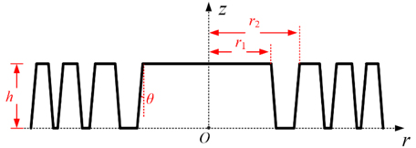
Inclination of the sidewall profile is unavoidable in the practice of fabricating FZP samples. The effects of sidewall angle of inclination on the focusing properties are discussed below. For simplicity, here we only consider the case where all sidewalls of the FZP have similar inclinations. The structure of an FZP with sidewall inclination is shown in Fig. 5, where
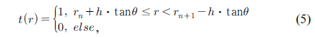
Considering the inclination of the sidewall, the transmission function of the transparent parts of the FZP can be expressed as:

where is the radius of zone
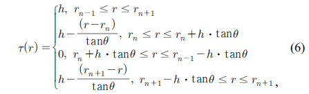
where
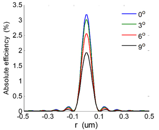
By introducing Eq. (7) into Eq. (1), the focusing properties of FZPs with different incline angles can be obtained by numerical calculations. Given the thickness of an FZP as 0.3 μm, for example, the influence of the sidewall inclination angle on the focusing properties of the FZP is calculated for similar structural parameters. As shown in Fig. 6, the results of calculation and simulation indicate that the absolute focusing efficiency of the FZP gradually increases with decreasing sidewall inclination angle. This is because the increase of sidewall inclination angle will result in the increase of the opaque part of the zone plate, thus reducing the focusing efficiency of the FZP. To obtain higher absolute focusing efficiency, the inclination of sidewalls should be reduced as far as possible during fabrication. The presence of sidewall inclination has little effect on the size of the focal spot.
3.3. The Effect of Metal Struts
For the FZP to be a self-supporting structure, it is often necessary to add a large number of metal struts in a radial distribution. These intentionally added struts may affect the focusing properties of the FZP, as discussed below.
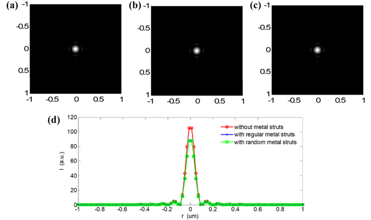
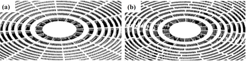
Figures 7(a) and 7(b) respectively show images of FZPs with regular and random metal struts. In the following numerical simulations, the same calculation parameters as in the first part of this section are selected, and the incline angle of sidewalls is assumed to be zero. Suppose a metal strut is added for every radial angle increment of
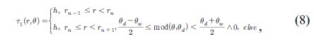
where
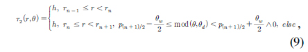
Similarly, the structure of an FZP with random metal struts 𝜏2(

where
By numerical simulations, the focusing properties of three kinds of FZP structures (no struts, regular struts, and random struts) are obtained, as shown in Fig. 8. By comparison, it is found that the focal-spot size of an FZP with metal struts is equal to that of the FZP without metal struts, and there is no side-lobe structure in the focal region. Therefore, the presence of metal struts only reduces the light-transmission area of the FZP structure and leads to a decrease of the focusing efficiency, but has little effect on other properties, such as the radius of the focal spot.
3.4. The Effect of Pulse Duration
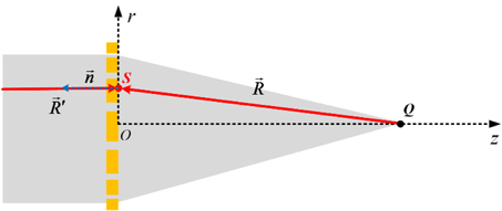
FZPs can arbitrarily be divided into objective and condenser zone plates. Objective FZPs are applied to form a small focus, generally consist of several hundred zones, and are several hundred nanometers in size. The task of a condenser FZP is to accumulate the maximum possible number of x-ray photons at the focus, and it is characterized by a large number of zones (

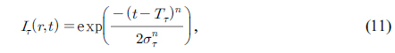
where is the time needed to transmit light from a point
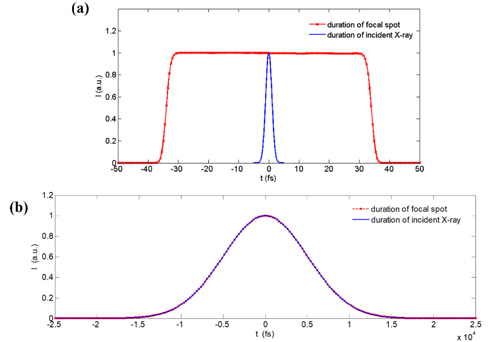
Figure 9 gives the results for the two cases above. It is found that the FZP elongates the pulse width by When choosing the related parameters in this paper,
In this paper, the influences of nonideal factors on the focusing properties of FZPs have been systematically studied by numerical simulations of scalar diffraction theory. In detail, the influence of the thickness on the focusing efficiency was calculated, for a given incident wavelength and material of FZP. It was found that choosing an appropriate thickness based on the incident wavelength
The diffraction efficiency and size of the focal spot were calculated for different inclination angles of the zone sidewalls. It was found that the absolute focusing efficiency of an FZP increases with decreasing incline angle, but the presence of inclination has little effect on the size of the focal spot. The effect of struts within FZPs (no struts, regularly spaced struts and randomly spaced struts) on the focusing properties was discussed, and it was found that the presence of metal struts only reduces the light-transmission area of the FZP structure and leads to decreased focusing efficiency. The struts have little effect on other properties, such as the radius of the focal spot.
The focusing characteristics of an FZP due to incident x-ray pulse duration at the focal spot were studied. It was found that the FZP (especially a condenser FZP) elongates the widths of incident ultrashort x-ray pulses. The work in this paper offers important guidance for design, processing, and application of FZPs.