


generally considered the most reliable and technically feasible way for the permanent disposal of High-Level radioactive Wastes (HLW). In an underground repository, the waste will be inserted in corrosion resistant canisters and be transported to disposal tunnels located several hundred meters underground. The deposition holes of the disposal tunnel will be excavated vertically in the floor or horizontally in the wall. The canister will be located in the center of the deposition hole with the surrounding buffer material. Normally, the open space of the disposal tunnel will be backfilled with suitable materials after canister installation.
In Korea, more than 11,000 tons of spent fuel has already been produced from the 21 nuclear power plants currently operating in four sites. The safe and reliable management of HLW is a national issue for the sustainable utilization of nuclear energy. Similar to other nuclear advanced countries[15], Korea has considered deep geological disposal as the most reliable way of managing HLW and developed a Korean Reference System, KRS, based on the characteristics of Korean geological conditions and waste. According to the KRS suggested in 2006, the underground repository for the permanent disposal of HLW, generated from 28 reactors during their life time, is planned to be located in a crystalline rock mass 500m deep underground [4]. The 36,000 tons of Pressurized Water Reactor(PWR) and CANada Deuterium Uranium reactor(CANDU) spent fuel will be inserted into 14,000 canisters after cooling for approximately 40 years. Each canister has a diameter and height of 1.22m and 4.8m, respectively. Recently, an Advanced KRS(A-KRS) was suggested as an alternative for disposing the waste generated from pyro-processing[5]. In the A-KRS, the repository will be constructed at two separate depths, 200m and 500m[6]. This concept modification will not substantially affect the approaches necessary in providing for canister isolation.
The KRS is based on the utilization of compacted bentonite as a major engineered barrier[4]. Because of its unique properties: (a) low hydraulic conductivity, (b) swelling capability, (c) elastic-plastic deformation behavior, (d) heat conducting properties, (e) high capacity for ion exchange, (f) chemically stable in severe disposal condition with heat and radiation, compacted bentonite is considered as a buffer material in many countries considering deep geological disposal of HLW. When bentonite is compressed to make compacted blocks, the thermal, mechanical and hydraulic properties will be altered significantly depending on the density, water content and mineral compositions. The properties of compacted bentonite had been investigated by previous studies. For example, Cho et al.[7][8] and Lee et al.[9] reported the thermal, hydraulic and mechanical properties of compacted bentonite from literature reviews and laboratory tests. Lee et al.[10] [11] also evaluated the properties of a bentonite-crushed rock mixture and bentonitesand mixture as candidate backfill materials. The canisters will be emplaced with compacted bentonite surrounding them in deposition holes, 2.2m in diameter.
Bentonite produced in Kyungju area will be compacted to make blocks for easy installation and to ensure the performance of the buffer. Kyungju bentonite is a Ca bentonite with approximately 70% montmorillonite The annulus of 0.5m between the canister and the hole surface will be filled with the
[Table 1.] Major Components in the Korean Reference Disposal System
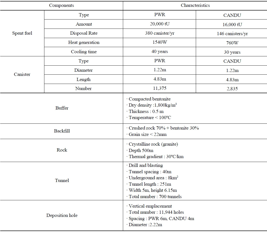
Major Components in the Korean Reference Disposal System
compacted bentonite. The open space of the disposal tunnel will be backfilled with a mixture of 70% crushed rock and 30% bentonite. Table 1 lists the characteristics of the major components in KRS.
Using available measured buffer and backfill properties, the long term performance of engineered barriers under geological disposal conditions has been investigated using computer simulations. For instance, thermal analysis of an underground HLW repository and thermo-mechanical analysis for a multi-level concept was already carried out[12][13]. Kim et al.[14] also performed thermo-mechanical modeling for a deep geological repository in a discontinuous rock mass.
In the present study, the thermal-mechanical coupling behavior in an underground HLW repository was analyzed to better understand the effects of the swelling pressure, water content in a buffer, selection of a plastic model, and the direction of the deposition hole on the stability of the canister, buffer, backfill and rock using three-dimensional computer models. In order to do that, the thermal and mechanical properties of the materials including the failure criteria of the buffer required for the complex modeling were determined.
The canister, buffer, and backfill are major engineered barriers used for the prevention of environmental contamination resulting from the release of the radioactive materials from waste after closure of the repository. Among the engineered barriers, the performance of the buffer is extremely important for achieving long term safety. Therefore, it is strongly recommended to use a material that can retain its thermal, hydraulic and mechanical capacities under harsh conditions, such as high temperatures, high pressures and high radiation levels expected in deposition holes. The unique properties of compacted bentonite as mentioned earlier are adequate for achieving the following roles of the buffer:
1)As a hydraulic buffer, it is important to have low hydraulic conductivity to retard the groundwater infiltration from the rock. The hydraulic conductivity of a bentonite block decreases with increasing density after compaction. In the deposition hole, the confining effect of the surrounding rock will also reduce the hydraulic conductivity when the bentonite blocks become saturated with water groundwater and swell.
2)As a mechanical barrier, the buffer needs to have the mechanical properties required to protect the canister from an impact or loading related to sudden movement or a steady time dependent displacement from the surrounding rock mass. It is also important that the buffer can hold the canister in the original position without serious displacement. When the bentonite buffer becomes saturated with groundwater, it acts as an elastic-plastic material that can effectively protect the canister from fractured rock movement. The swelling of bentonite expected with the suction of water can help enhance the mechanical and hydraulic stability by filling the fractures around the deposition holes.
3) One of the most critical design criteria for a HLW repository is the peak temperature at the interface of canister and buffer. To ensure the performance of bentonite buffer, the repository needs to be designed to ensure that the peak temperature is lower than 100℃. The buffer should be a good thermal conductor to transfer the heat effectively from the waste to the rock.
4) The radioactive materials can escape from the repository if the canister containing HLW malfunctions for some reason, such as corrosion or rupture and a pathway is available from the canister location to the surface. In such a situation, a low diffusion coefficient of buffer will be helpful in retarding the release rate of radioactive materials until substantial radioactive decay has occurred. The above-listed properties are of relevance to many international programs examining options for deep geological disposal of HLW. As a result, in situ experiments, such as FEBEX (Full scale Engineered Barrier EXperiment)[1] and LOT (Long Term Test of Buffer Material) experiments in crystalline rock[2] and EB (Engineered barrier emplacement experiment) in opalinus clay,[3] have been carried out to assess the feasibility of using compacted bentonite as a buffer.
Although located a greater distance from the canister, the roles of backfill are similar to those of the buffer except for the mechanical protection of a canister. Backfill, however, does not necessarily need to have the same functional capabilities expected in the buffer, but for the KRS it is recommended to be able to sustain the severe pressure from the buffer-filled deposition hole and the adjacent rock. For backfill, different options involving combinations of bentonite, crushed rock and sand have been developed.
2. PROPERTIES OF BUFFER AND BACKFILL
Cho et al.[7] reported the thermal properties of the compacted buffer and backfill manufactured from Kyungju bentonite with different water content w(%). The chemical composition of the bentonite is 56.8% SiO2, 20.0% Al2O3, 6.0% F2O3, 2.6% CaO, 0.8% MgO, 0.9% K2O, 1.3% Na2O, 0.2% FeO, 1.3% SO3 and 0.8% TiO2 [16].
1)Thermal conductivity, K(w/m°K)
- buffer with a dry density of 1800kg/m3 : K = 0.0584w + 0.4738
- backfill with a water content(w) of 17% : K = 2.04
2)Specific heat, C(kJ/kg°K)
- buffer with a dry density of 1800kg/m3: C=(32.3+ 4.18 w) / (100+w)
- backfill : C=(34.1+4.18 w) / (100+w)
3) The thermal expansion coefficient of the buffer with a dry density of 1200-1600 kg/m3 is 3.1 x 10⁻⁴
When the dry density of bentonite is more than 1600 kg/m3, the hydraulic conductivity in fresh water is <10-12 m/sec. Hydraulic conductivity normally increases with increasing temperature because of the change in fluid viscosity with temperature. The hydraulic conductivity of compacted bentonite at 80℃ was reported to be 3-4 times higher than that measured at 20℃[17]. The swelling pressure expected in compacted bentonite when it absorbs water is important in the design of a repository system. From the in situ test carried out using Na-bentonite compacted to a saturated bulk density in the order of 2000-2100 kg/m3 in the Stripa mine in Sweden, where the groundwater was of low salinity, it was found that the swelling pressure was 10MPa[22]. Normally, compacted Ca-bentonite has similar properties to Na-bentonite except for a lower swelling pressure.
The mechanical properties, such as compressive strength, elastic modulus, cohesion, Poisson's ratio and angle of internal friction were measured from laboratory tests using compacted Kyungju bentonite under a range of test conditions. Table 2 lists the mechanical properties of the buffer and backfill.
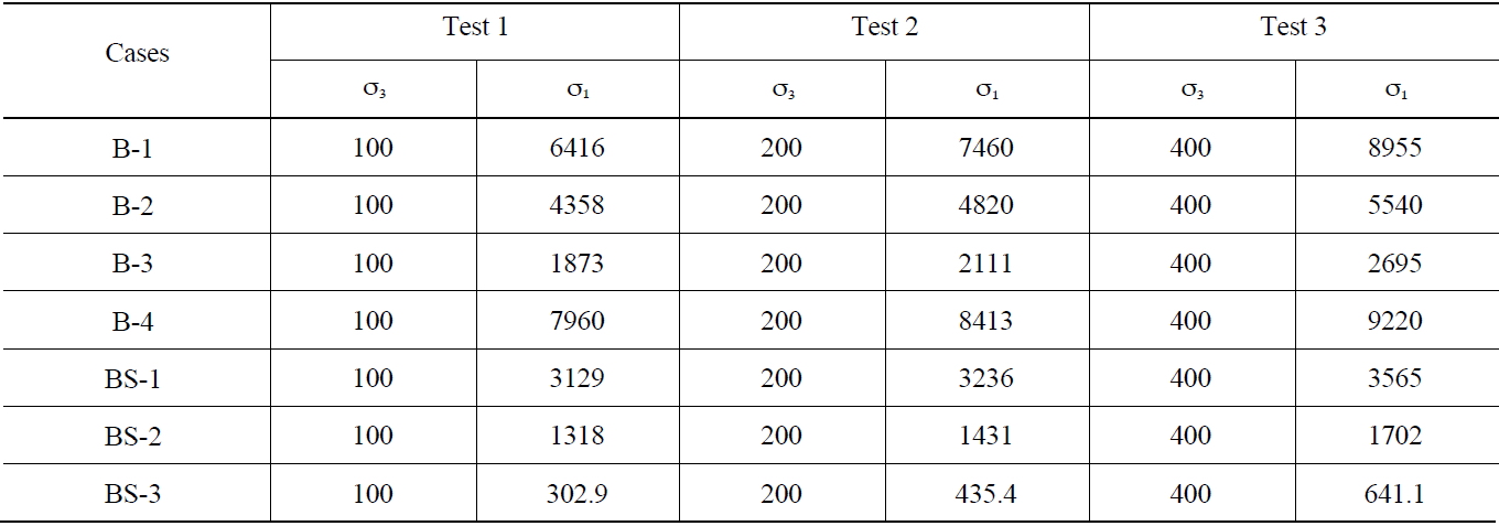
2.4 Failure Criteria of Buffer and Backfill
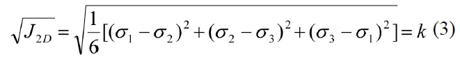
The buffer and backfill are inevitably under a load from excessive pressure, thermal stress, hydraulic pressure and swelling pressure. The pressure from the surrounding rock and groundwater at several hundred meters is quite high compared to the strength of the buffer and backfill. Furthermore, there will be a stress concentration at certain locations due to a stress redistribution after excavating the tunnel and deposition hole. The stress redistribution pattern depends on the initial stress condition, rock properties and repository design. Under severe loading conditions, the buffer and backfill will behave as plastic materials. To predict their elastic-plastic behavior, adequate failure criteria should be defined using triaxial compression tests. In this study, the failure criteria of the buffer and backfill were determined from triaxial compression tests under different conditions, as listed in Table 3[18]. Using the test results listed in Table 4, the parameters for the different failure criteria, such as (a)Mohr-Coulomb failure criterion; (b) Tresca failure criterion; (c) Von Mises failure criterion; and (d) Drucker-Prager failure criterion, could be defined and are listed in Table 5;
1) Mohr-Coulomb failure criterion

2) Tresca failure criterion
[Table 2.] Mechanical Properties of Buffer and Backfill
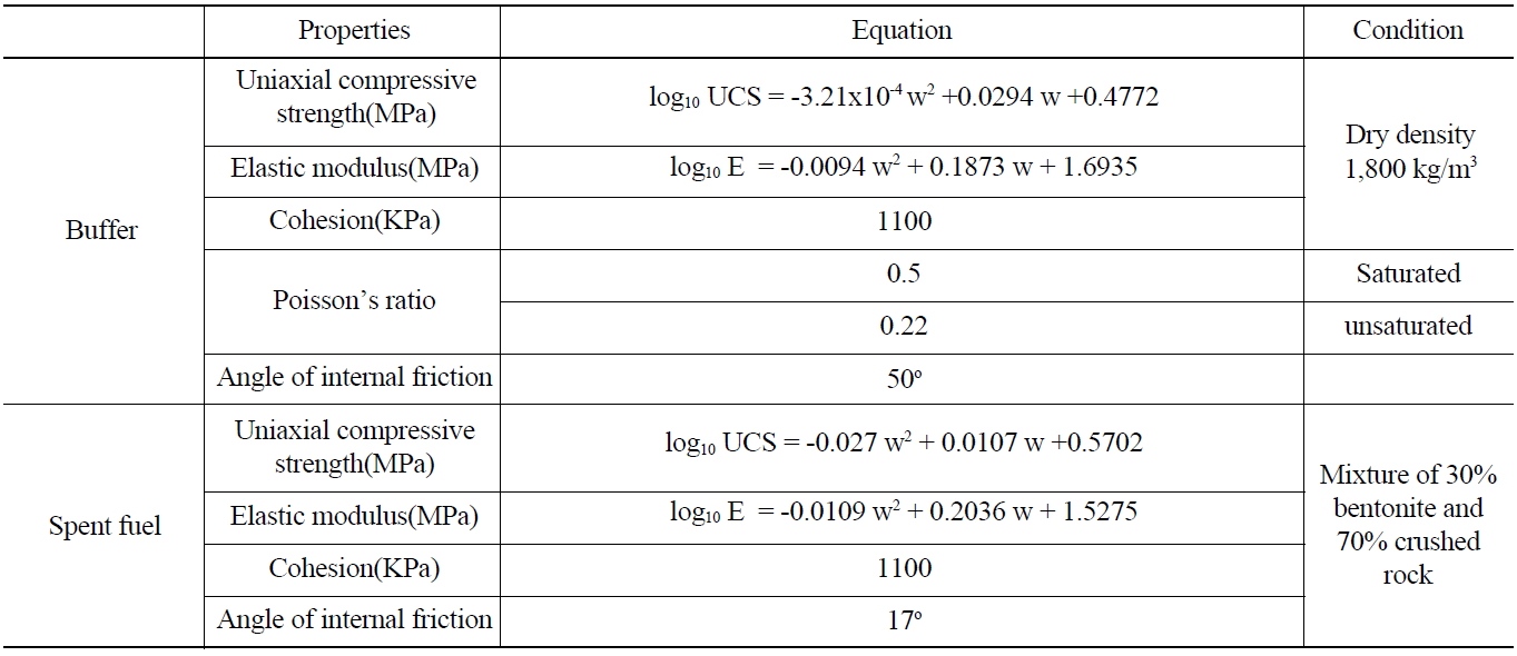
Mechanical Properties of Buffer and Backfill
3) Von Mises failure criterion
4) Drucker-Prager failure criterion

where,
3. THERMAL-MECHANICAL MODELING
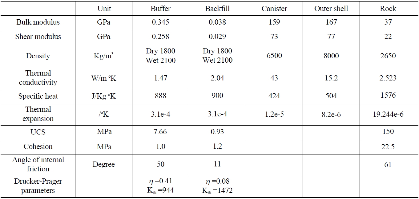
In the model, the thermal and mechanical properties required for Thermal-Mechanical analysis were determined under the assumption of a buffer containing 17% water and a compacted density of 1800kg/m3(Table 6). The properties of the rock in the table were measured from laboratory tests using the rock cores acquired from the Kosung area in Kangwon province[19]. The rock type was granite with elastic modulus of 56.6GPa and Poisson’s ratio of 0.25. The geothermal gradient and in situ stress ratio change with depth were also measured at the area.
[Table 3.] Buffer and Backfill Testing Conditions

Buffer and Backfill Testing Conditions
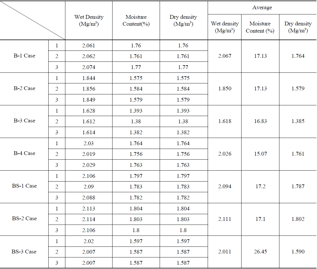
[Table 4.] Results from Triaxial Compression Tests (unit: kPa)
Results from Triaxial Compression Tests (unit: kPa)
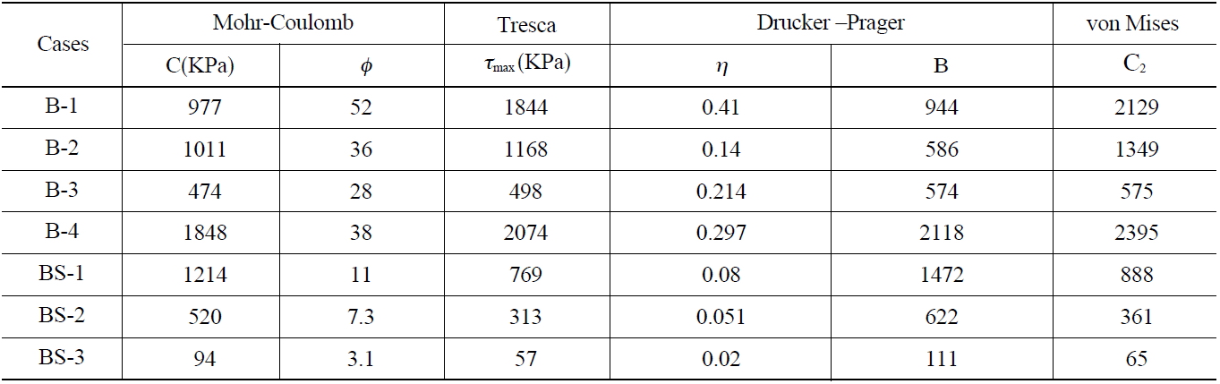
[Table 5.] Failure Parameters for Different Failure Equations for Buffer and Backfill

Failure Parameters for Different Failure Equations for Buffer and Backfill
[Table 6.] Material Properties of Buffer, Backfill, Canister and Rock Used in the Modeling

Material Properties of Buffer, Backfill, Canister and Rock Used in the Modeling
Heat loss through the surface was considered with the heat convection coefficient of 0.7 W/m2K, which is suitable for natural convection. Since the mechanical properties of a rock mass with discontinuities, such as fractures, faults and bedding planes, are normally different from those of the intact rock, the following equations were used to estimate the bulk modulus(Kmass)and shear modulus(Gmass) of the rock mass[20].
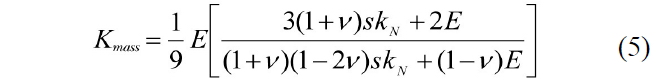
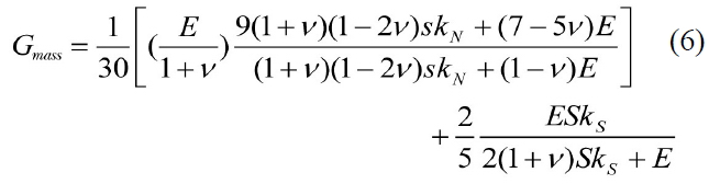
where E and ν are the elastic modulus and Poisson’s ratio of intact rock, s is the joint spacing, and kn and ks are the normal and shear stiffness of discontinuities, respectively.
In this study, it was assumed that PWR spent fuel with a burn up of 45,000MWd/tHM is disposed in a 500m deep underground. The decay heat from the PWR spent fuel with time can be calculated using the following equation:

where t is the cooling time(years) after release from the reactor. The assumption in this model was that four assemblies are to be inserted in a single canister after allowing 40 years of cooling. Since the model focuses mainly on investigating the behavior of the engineered barriers, the complex structures and properties of the spent fuel and cast iron inside the canister can be simplified as a uniformly

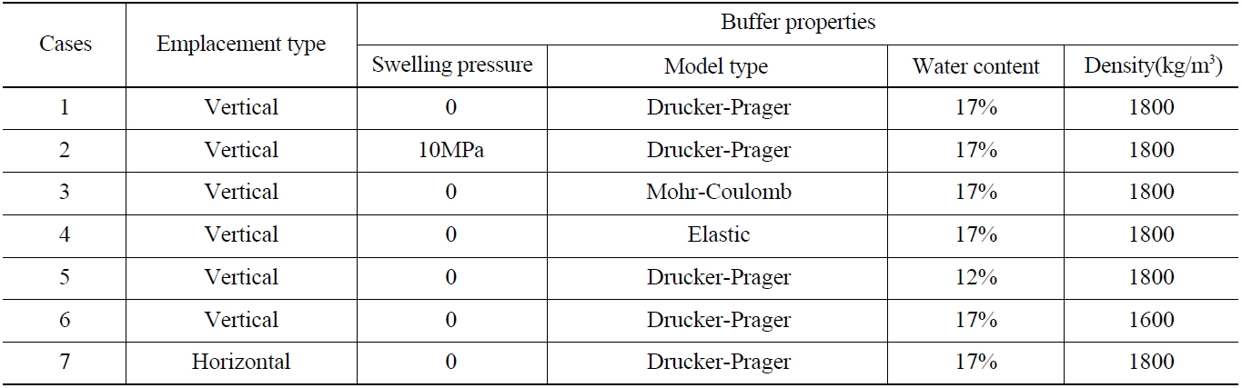
Modeling Cases
mixed inner part. The mean thermal and mechanical properties of the inner part of the canister were determined at a volume ratio between the fuel part and cast iron part. The outer shell of the canister is made of corrosion resistant metal with a density of 8000 kg/m3.
3.2 Initial and Boundary Conditions
The initial in situ stress condition was considered to be hydrostatic, based on the measurements that showed the stress ratio was about 1.0 at 500m depth. The temperature distribution in the model was calculated with the geothermal gradients of 37.5℃/km measured at the Kosung site[19] and the assumed surface temperature of 20℃. Even though there will be a time interval between the tunnel and deposition hole excavations, it was assumed that they are excavated simultaneously. After excavation of the openings, mechanical calculation was carried out until the rock became stable with stress redistribution. After completion of stress redistribution, the buffer, canister, and backfill components were installed and further thermo-mechanical analysis with the decay heat generation was completed. The rock was assigned as Mohr-Coulomb model with a cohesion of 22.6MPa and an internal friction angle of 61°. The fuel-filled portion of the canister and its outer shell were assumed to be elastic. The excavation damaged zone that may be present in the rock around the tunnel and deposition hole was not considered in this study. To further simplify the modeling complexity, the interfaces between the fuel part and outer shell, canister and buffer, buffer and rock, and backfill and rock were assumed to be in tight contact. Zero heat flux and zero normal displacements were assigned at the boundaries except the top surface.
Table 7 lists the cases covered in this study to examine the effect of parameters, such as the failure criteria, water content, compaction density, swelling pressure and emplacement type. A horizontal emplacement was included for comparison with the vertical emplacement, which is the reference emplacement type in the KRS. In the horizontal case, many canisters were assumed to be disposed of in a long horizontal deposition hole. Case 1 is the reference modeling case with a buffer containing 17% water, compaction density of 1800kg/m3, zero swelling pressure, and Drucker-Prager failure criterion, in which the effects of the intermediate principal stress,
3.4 Modeling Result for the Base Case
FLAC3D is a commercial code adapting fast Lagrangian analysis provided by Itasca Consulting Group and widely used in various civil and mining engineering projects. Using finite-difference method(FDM), which is suitable for large, non-linear problem which may involve collapse or progressive failure, FLAC3D can offer a wide range of capabilities to solve thermal, mechanical, and hydraulic problems. It also contains a powerful built-in programming language FISH, that allows the users to define new variables and functions. In this study, therefore, the non-linear plastic behavior expected in buffer and backfill under disposal conditions was solved using FLAC3D 3.2[21].
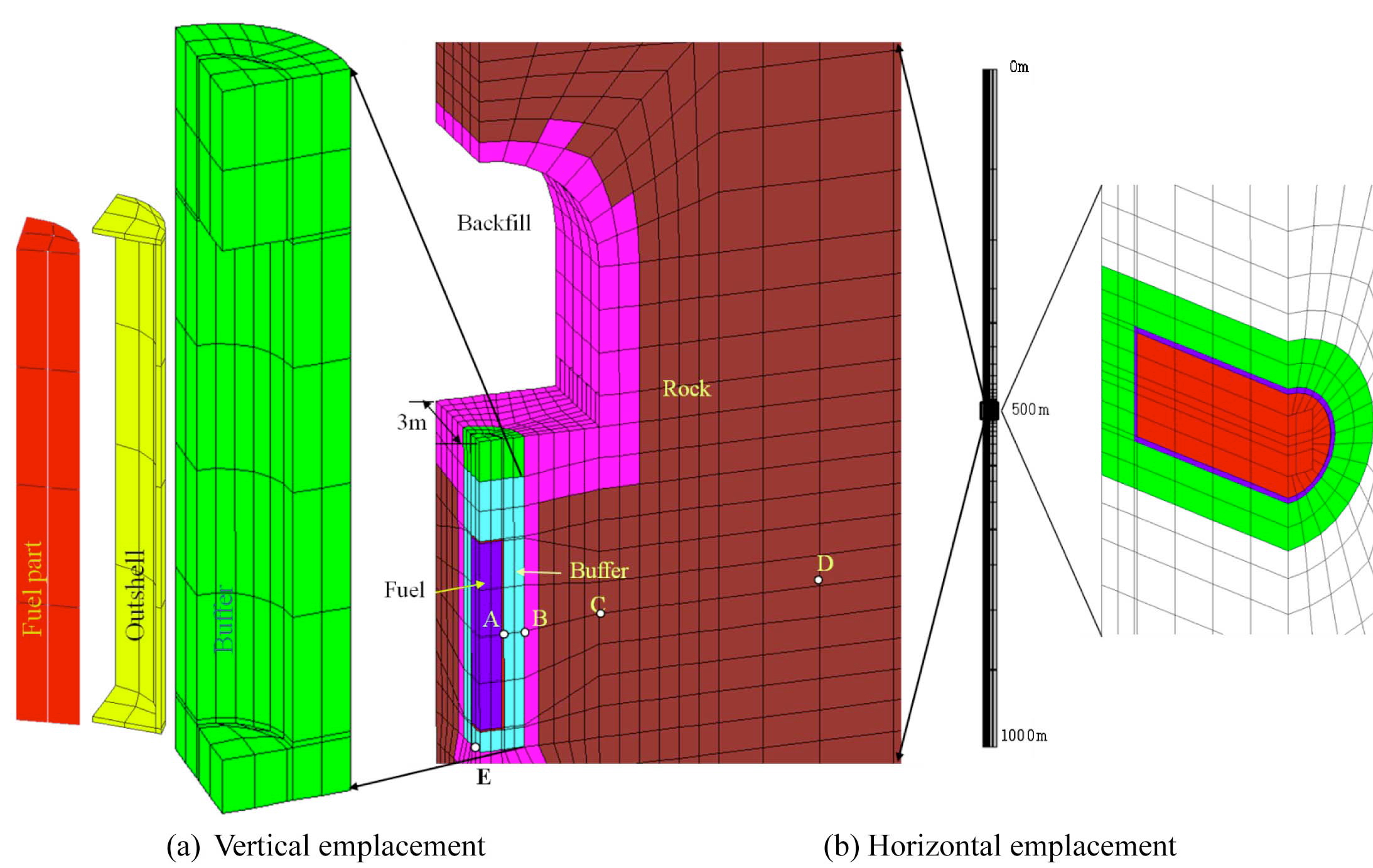
Fig. 1 shows the model mesh for the vertical and horizontal emplacement cases. In the model, a 5cm thick outer shell of the canister was also included to examine the influence of a stress change due to a rock displacement as well as thermal stress. The model mesh consisted of approximately 6000 zones and 8000 grids. A 1500m thick rock mass, 500m above and 1000m below the repository, was modeled to observe the long term thermal and mechanical behavior. In the modeling, the thermal-mechanical coupling occurs only in one direction: temperature changes cause thermal strains to occur which influence the stresses, while the thermal calculation is unaffected by the mechanical changes.
1)Thermal behavior
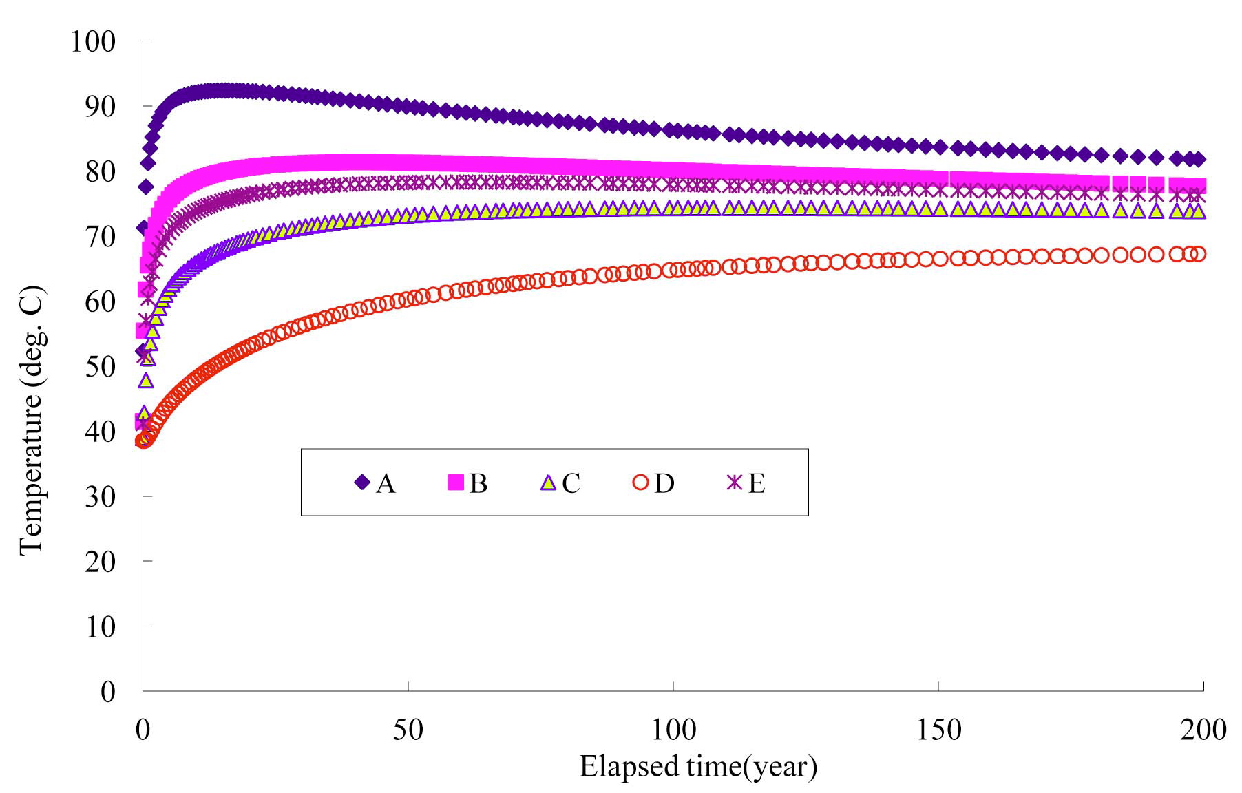
Fig.2 shows the temperature variations at the four locations (A, B, C, D and E) in Fig.1. With the decay heat from the waste, the temperature at the locations increases with time. At point A, the temperature in
the interface of the canister and buffer increases most rapidly to a peak temperature of 93℃, which would be expected in approximately 17 years after disposal. The temperature decreases steadily after arriving at the peak value. At point B, a peak temperature of 81℃ is predicted after 40 years. At points C, and D, the temperatures are expected to peak after more than 100 years. At point E in the floor of the deposition hole, a peak temperature of 78℃ is expected in approximately 60 years after disposal.
2)Mechanical behavior
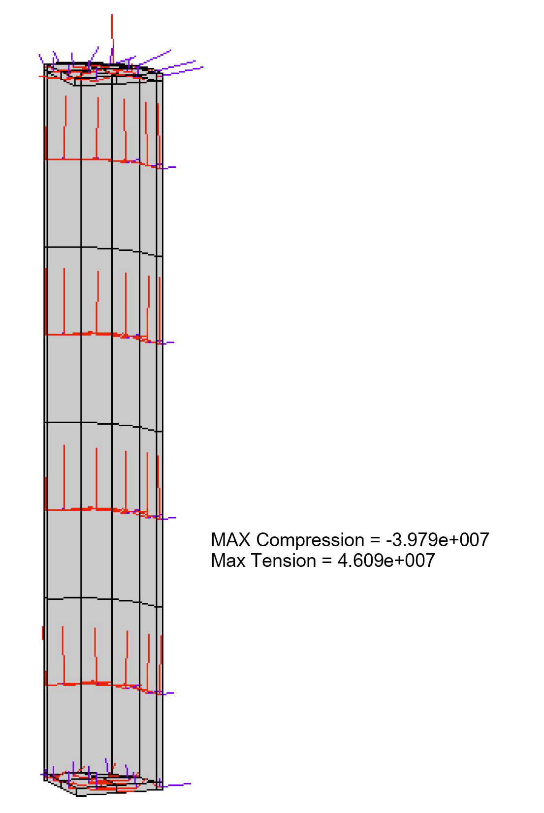
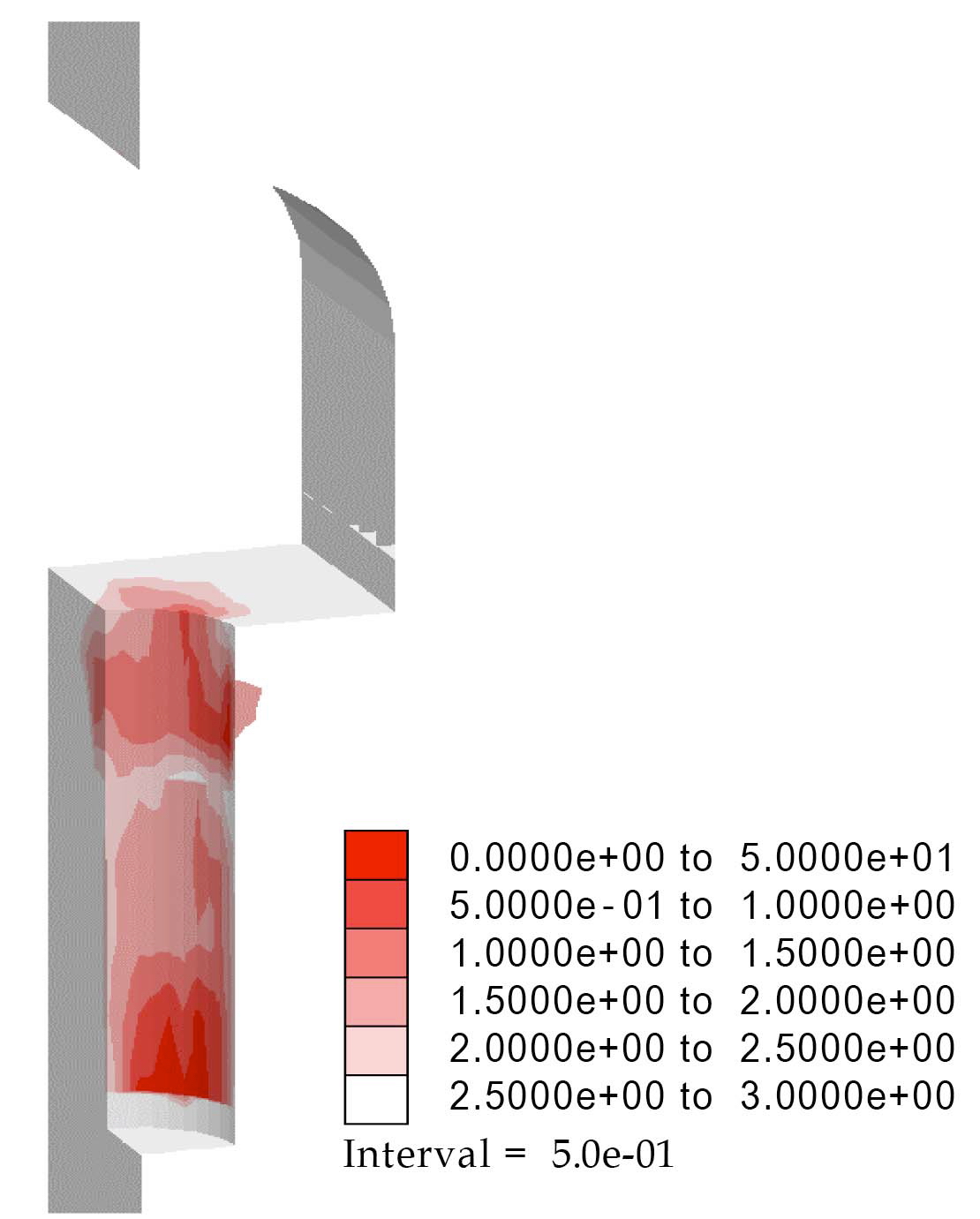
The stress distribution is important for understanding the mechanical stability of the disposal system. Fig.3 shows the distribution of principal stress in the canister’s outer shell at 50 years after disposal. A maximum tensile stress of 46MPa develops along the axial direction due to the thermal expansion of the inner part of the canister. Such a tensile stress along the axial direction can easily expand the fractures lying horizontally. This suggests that the selection of outer shell material and manufacturing technique of the canister is important for preventing ruptures in the outer shell during the designated lifetime of the canister, especially when the cast iron and outer shell are tightly contacted. To evaluate the mechanical stability of the underground
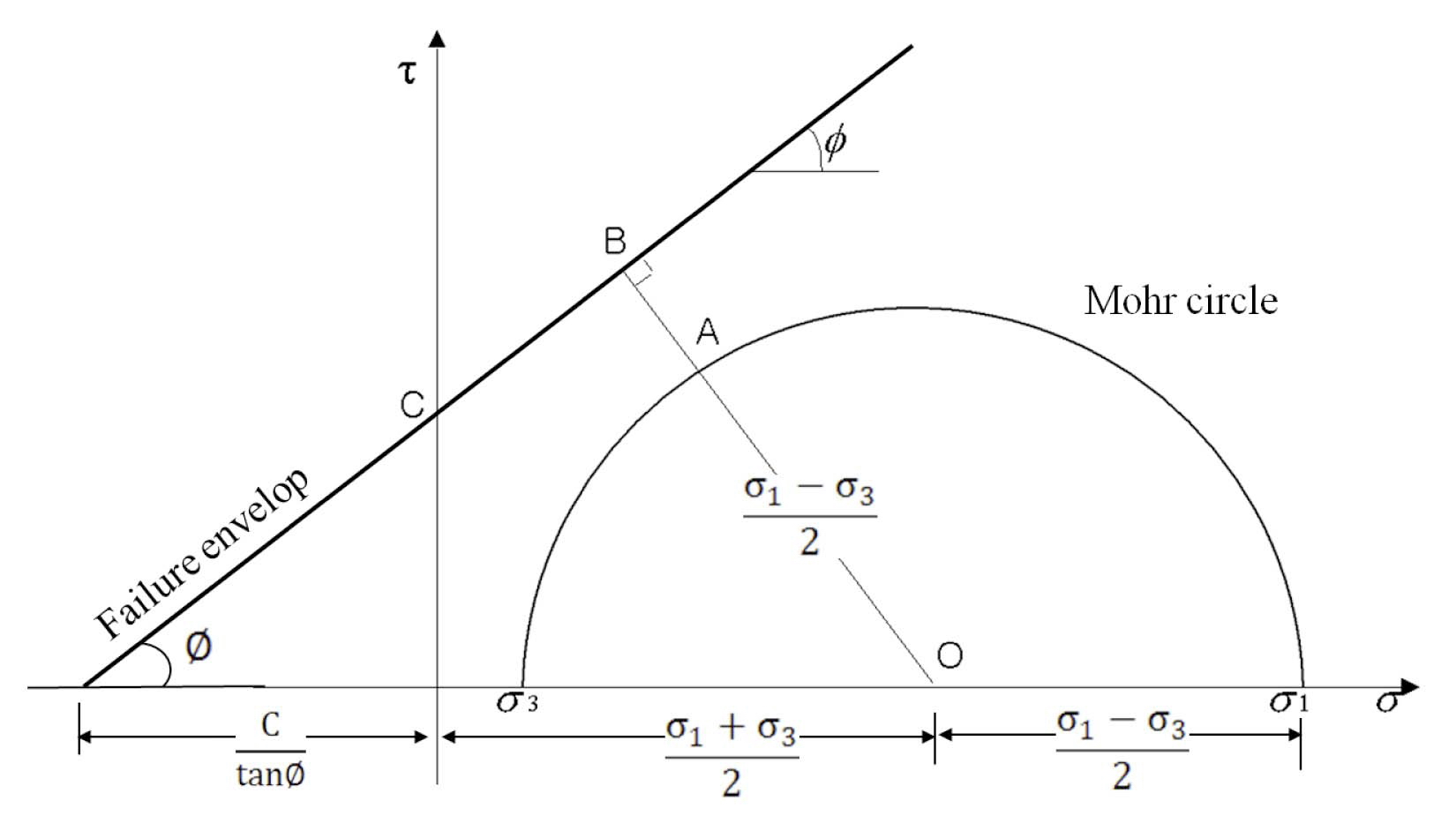
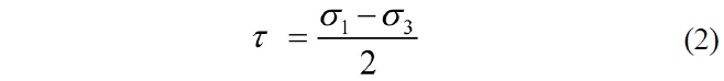
repository, a factor of safety(FS) should be calculated. Fig.4 shows the method for estimating the factor of safety using the Mohr-Coulomb failure envelope. If the major and minor principal stresses are known at a certain location, the factor of safety at that location can be calculated using the following equation:
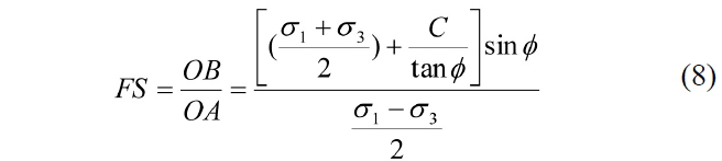
where,
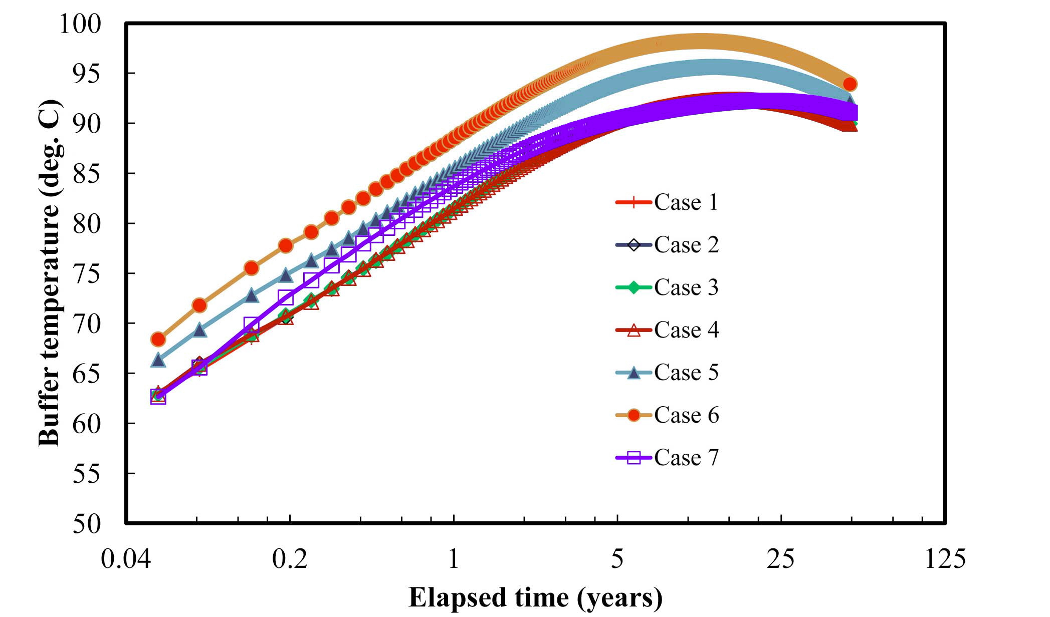
[Fig. 6.] Variation of Temperature with Time at the Canister and Buffer Interface (Point A in Fig.1)

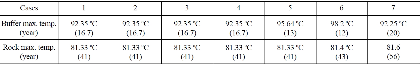
[Table 8.] Peak Temperature and Time in the Buffer and Rock

Peak Temperature and Time in the Buffer and Rock
3.5 Comparison between the Cases
The thermal and mechanical results in 50 years were compared to examine the effects of the design parameters used in different cases. In each case, the maximum buffer temperature was reached before 50 years, as shown in Fig.6. Depending on the design parameters, there was an approximately 6℃ difference in the peak temperature. Table 8 lists the peak temperatures and peak time in the buffer and rock. In the buffer, the peak temperature was recorded in between 12 years to 20 years after emplacement. The maximum temperature was predicted in case 6, where a lower density buffer was used. More heat appears to have accumulated in the deposition hole because of the lower thermal conductivity of the less compacted buffer. This can explain the late arrival time to the peak rock temperature in case 6.
Compared to the cases for vertical emplacement, the case for horizontal emplacement showed a slightly lower peak temperature and slow arrival time to the peak value in the buffer and rock. This was attributed to the difference in the length of the deposition hole. Since it was not needed to consider the effects of backfill in a long horizontal deposition hole concept, the decay heat might be dispersed more easily through the rock. The peak rock temperatures in all of these cases were similar. This means that the variations in the design of an engineered barrier will have less effect on the peak rock temperature compared to the peak buffer temperature.
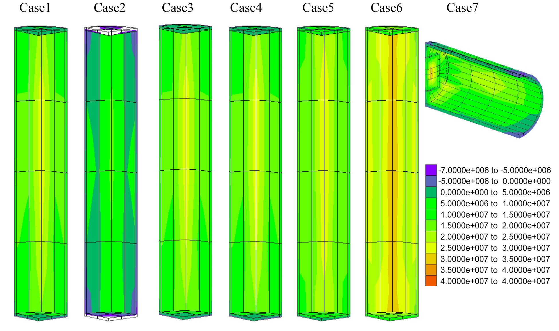
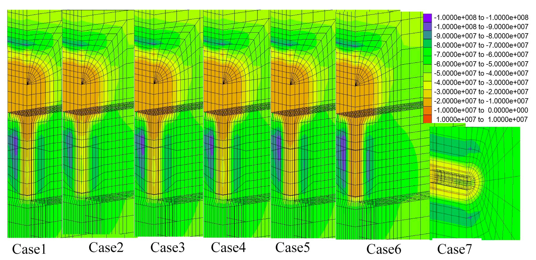
Fig.7 compares the distribution of principal stress in 50 years. In the vertical emplacement cases, the maximum compressive stress of approximately 100MPa was observed
in the rock pillar between the deposition holes. In contrast, the stress was only 80MPa in the horizontal case without a rock pillar.
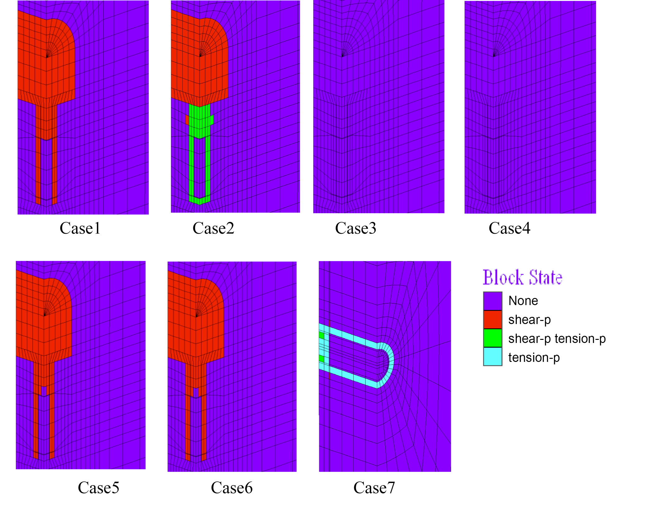
Fig.8 shows the development of a plastic zone in the engineered barrier in each case. Some rock failure could be observed, as expected in case 2, in which a swelling pressure of 10MPa was considered. In most cases, the buffer and backfill failed within 50 years. On the other hand, no plastic zone was observed in case 3, in which the Mohr-Coulomb failure criterion had been used. This suggests that it is less conservative to use the Mohr-Coulomb failure criterion, which cannot consider the influence of the intermediate principal stress. Since the failure and plastic deformation in the engineered barrier can differ according to the plastic model, it is important to select the failure criterion more carefully for a better evaluation of the disposal system.
Fig.9 shows the minor principal stress distribution in the outer shell of the canister. Similar to the reference case, a tensile stress developed in all cases. One interesting observation was the lower tensile stress in case 2 due to the swelling pressure acting from the surrounding buffer. This suggests that the swelling pressure, uniformly loaded from the buffer, can enhance the mechanical stability of the outer shell.
In an underground HLW repository, where there is high in situ stress and hydraulic stress several hundred meters deep underground, thermal stress related to the decay heat from the waste and swelling pressure from the buffer are expected over a long period of time. For optimal design of the repository system, the effect of the design parameters should be analyzed carefully considering the possible loading conditions. In this study, the thermal and mechanical behavior of the engineered barriers including the canister, buffer and backfill, and natural barrier under the expected loading conditions in the KRS were modeled using three-dimensional computer code, FLAC3D. For the computer simulation, the thermal and mechanical properties of the buffer, backfill, canister and rock were derived from previous studies. Furthermore, the parameters in various failure criteria could be determined from the triaxial compression tests for the buffer and backfill made from Kyungju bentonite under different testing conditions. For a more reliable simulation, the rock properties and in situ conditions measured at the Kosung site in Kangwon province were used. From the simulation for different cases, the effect of the emplacement type, swelling pressure, plastic model, and water content in the buffer on the stability of engineered and natural barriers could be investigated. From this study, the following conclusions could be drawn:
1)Careful selection of the material type and manufacturing technique of the canister is needed because a significantly high tensile stress along the axial direction of the outer shell of the canister is possible due to thermal expansion of the canister. This is especially true when the outer shell and fuel components are tightly contacted.
2)The tensile stress on the outer shell can be reduced considering the swelling pressure from the compacted buffer. The swelling pressure effect should be included for more detailed modeling in the future.
3)The water content and density of bentonite should be considered as important design parameters because these significantly affect the thermo-mechanical behavior of the engineered barriers.
4)In the cases of vertical disposal in the tunnel floor, a peak buffer temperature of approximately 95℃ can develop within 20 years after emplacement. On the deposition hole surface, the peak rock temperature was approximately 10℃ lower than the peak buffer temperature, and the peak time was also delayed to 40 years. The horizontal emplacement case showed a lower peak temperature and slow arrival time to the peak values. The decay heat might be dispersed more easily through the rock mass, because the influence of backfill can be neglected in a long horizontal deposition hole concept.
5)Depending on the water content and buffer density, the peak buffer temperature was changed from 92℃ to 98℃. In contrast, there was much less influence on the peak rock temperature.
6)Although the same laboratory results were used to drive the parameters for the plastic models used in the model, the mechanical behaviors were different. Therefore, it is important to use appropriate plastic models for the buffer and backfill materials.