


Collision and grounding accidents occur at sea in spite of continuous efforts to prevent them. The collision and grounding accidents of liquid cargo tankers such as crude oil carriers and chemical tankers cause the structural damage of ships and pollute the ocean environment. Therefore, regulations for ship structural design against the severe accidents have been developed to reduce ocean pollution and the loss of human safety.
The goal-based standard (GBS) being developed by the international maritime organization (IMO) requires the longitudinal strengths for both intact and damaged ships with major damages due to collision and grounding accidents. The compartments of a ship can be flooded due to the failure of shell plating, forcing the ship to heel at a certain angle. The damaged ship should be able to withstand the heeling without any catastrophic hull girder collapse until it reaches the closest harbor. Therefore, the identification of the residual longitudinal strength is very important.
Many studies have focused on predicting the residual longitudinal strength of damaged vessels. A simple procedure for hull girder strength estimation after collision and grounding damage was proposed by Paik et al. (1998). The procedure is regarded as suitable in the early design stage. Prediction formulas based on the hull girder section modulus were suggested for the prediction of the residual longitudinal strengths (Wang et al., 2002). The combined loading effect on the ultimate strengths of a bulk carrier under alternate hold loading conditions using nonlinear FEA was studied by Amlashi and Moan (2008). The ultimate vertical bending moment capacity was studied by nonlinear FEA (Paik et al., 2008). But it should be noted that far too many resources for modeling and computing are required for nonlinear FEA. The idealized structural unit method (ISUM) has been taken as one of the alternative methods. Paik et al. (1996) insisted that ISUM substantially reduces modeling efforts, especially for initial imperfections and residual stresses. The hull girder residual strengths of four double-hulled tankers, three bulkers, and one single hull very large crude carrier (VLCC) with assumed grounding damages were proposed using ISUM (Wang et al. 2000). The iterative-incremental method (IIM) which is also called progressive collapse method (PCM), based on the principles of the Smith method (Smith, 1977), has primarily been applied to estimate the hull girder strengths of intact ships (Gordo and Guedes Soares, 1996; 1997; Gordo et al. 1996; IACS, 2010). Nielsen (1998), Cho and Lee (2005), Smith and Pegg (2003), Fang and Das (2004), Jia and Moan (2009), Khan and Das (2008), and Hussein and Guedes Soares (2009) tried to apply PCM to the asymmetrically-damaged sections, but they failed to provide a relationship between heeling angle (or moment acting plane) and angle of rotated neutral axis. Using PCM, Choung et al. (2012) derived the ultimate hull girder residual strengths of a VLCC in which mechanically perfect convergence criterion for neutral axis rotation was proposed.
For the calculations of the residual ultimate strengths, this paper will basically apply new PCM by Choung et al. (2012). IMO Guidelines (2003) provide probabilistic damage extent of oil tankers to estimate the amount of oil spilled from the 52 collision and 63 grounding accidents of oil tankers, chemical tankers, and ore carriers of 30,000
In this paper, a VLCC designed according to the CSR for Tankers (IACS, 2010) is chosen as a target vessel to calculate the residual longitudinal strengths. Probability levels of 10%, 30%, 50%, and 70% are taken into account for defining the extent of the damage. The residual longitudinal strengths are presented for all possible heeling angles with 15° increments from sagging to hogging conditions.
A NEW PROGRESSIVE COLLAPSE METHOD
The progressive collapse method assumes that a hull girder failure is the result of an inter-frame collapse of the ship structure. The key assumption is based on Navier’s hypothesis. In the design calculation of beams, it states that the stress at any point due to bending is assumed to be proportional to its distance from the neutral axis. This implies equivalently that the plane of the cross-section is assumed to remain a plane under continuous curvature or moment increase. A hull girder section is subdivided into small structural units, which are often called stiffened panels and are assumed to behave independently. The neutral axis plane (NAP) of the cross section should be located at an equilibrium position of the axial forces. The total moment resistance of the section is determined by the summation of the unit forces times their perpendicular distance to the neutral axis.
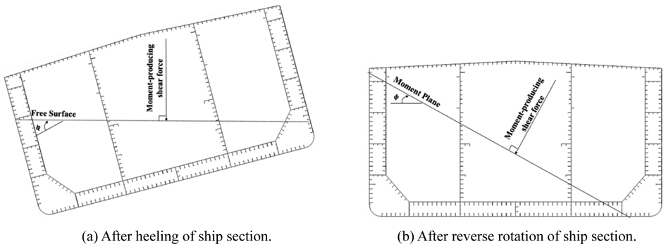
The limit of the classical principle of PCM is that it can’t be applied to the asymmetric section, because it is impossible to recognize how much NAP simultaneously rotates and translates during inelastic deformation of the structural units such as yielding and post-buckling. Asymmetry of the section can be easily produced by heeling of the section or collision-induced shell damage. Many researchers have tried to apply classical PCM to the asymmetrically-damaged sections due to collision or groundings. Smith and Pegg (2003) assumed that the angle of NAP was same as the angle of the moment-acting plane. However, it is apparent that even the angle of elastic NAP deviates from the angle of the moment-acting plane. Cho and Lee (2005) assumed that the angle of elastic NAP remained during inelastic deformation. This assumption is also mechanically incomplete.
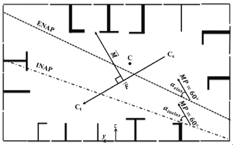
In order to produce mechanically complete solution, Choung et al. (2012) proposed a new convergence criterion for the angle of NAP rotation with several new definitions of moment planes (MPs) and elastic and inelastic NAPs. Hereafter, this is called INAP.
For the ship section with a heeling angle
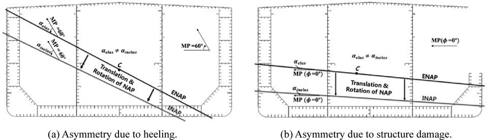
An elastic neutral axis plane (ENAP) is defined as one when any structural unit does not undergo inelastic deformation with respect to axial behaviors, such as yielding under tension or buckling under compression. For asymmetric sections, ENAP always passes through the centroid of the section, but is not parallel to MP. Only for perfectly symmetric sections is ENAP parallel to MP. If any of the structural units shows inelastic effects, the inelastic neutral axis plane (INAP) is defined as the plane in which compressive and tensile forces are in equilibrium.
Buckling and yielding will dominate behaviors of the structural units, respectively. Since buckling resistance is usually less than yielding resistance, the INAP of the symmetric section tends to move up for a hogging moment or down for a sagging moment. The INAP of the asymmetric section moves and rotates in any direction. In other words, the INAP of the asymmetric section cannot pass through the centroid of the section due to translation of the INAP, and cannot be parallel with the ENAP due to the rotation of the INAP.
The NAP of the symmetric section will translate only in the vertical direction. An algorithm for finding the NAP of the symmetric section is well defined in common structural rules (IACS, 2010). Namely, at each increment of the external moment, NAP should be located to satisfy Eq.(1).
But in the case of an asymmetric section because of heeling to
Ultimate moment analysis of damaged ships (UMADS), a newly-developed in-house program applying both convergence criteria, is capable of evaluating the ultimate strengths of intact and damaged hull girder sections. In this paper, all the calculations are performed using UMADS. The convergence factor


PROBABILISTIC DAMAGE EXTENT AND LOCATIONS
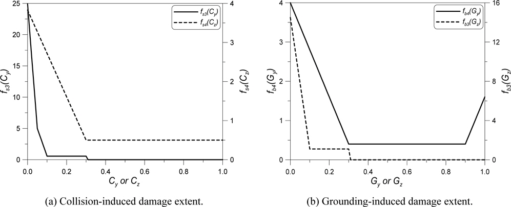
Major damages due to ship collision and grounding are described in some references (ABS, 1995a; 1995b; DNV, 2009). However they are all prescriptive, and do not provide probability of occurrence or survival. Lüzen (2001) collected damage data from a European joint project (HARDER) and proposed distributions for each damage extent. However, there was no descripttion on the collision-induced vertical damage extent. Tagg et al. (2002) proposed vertical damage extent with the assumption that side structures below the water line were completely broken. Zhu et al. (2002) provided grounding-induced damage extent from Ro-Ro ship accidents, but not vertical damage extent. Even if Pedersen and Zhang (2000) pointed out that longitudinal damage extent due to grounding were underestimated, this paper principally utilizes PDFs of the probabilistic damage extent defined in IMO Guidelines (2003).
All damage components are normalized by corresponding principal dimensions. For instance,


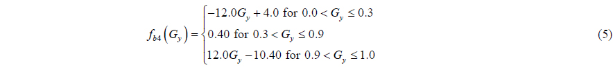
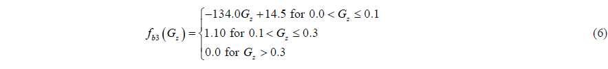
Eqs. (7) and (8) forecast collision-induced damage locations in longitudinal and vertical directions, while groundinginduced damage locations in longitudinal and transverse directions are shown in Eqs. (7)-(9). From Eq. (7), even probability along the ship length is produced. However, it should be noted that concerning part is amidships, because the maximum hull girder bending moment occurs approximately midship. Eq. (10) implies that any transverse location can be a candidate for a grounding accident.


RESIDUAL LONGITUDINAL STRENGTH ASSESSMENTS OF A DAMAGED VLCC
In this paper, a VLCC is chosen for comparative studies. The main dimensions of the vessel are listed in Table 1. We take into account five damage probability levels of 0% (intact), 10%, 30%, 50%, and 70% based on IMO Guidelines (2003). IACS (2010) simplified formulae are used for the prediction of the average compressive strength of the structural unit (stiffened panel).
[Table 1] Dimensions of the VLCC.

Dimensions of the VLCC.
where LBP : length between perpendiculars B : moulded breadth D : moulded depth TSC : scantling draft l : frame space
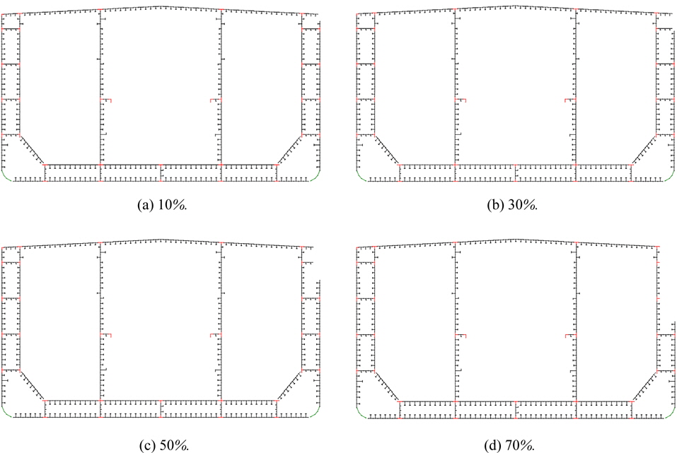
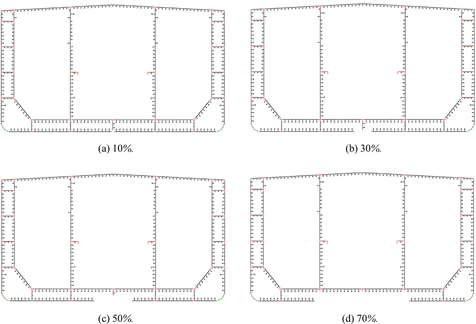
Table 2 shows the damage extent for the collision and grounding of the VLCC and applies the IMO Guidelines (2003) to the probabilistic damage level. Figs. 5 and 6 show the damage extent according to the probabilistic damage level by collision and grounding, respectively
[Table 2] Damage extent due to collision and grounding.
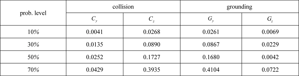
Damage extent due to collision and grounding.
>
Residual strength assessment
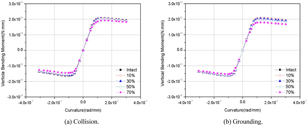
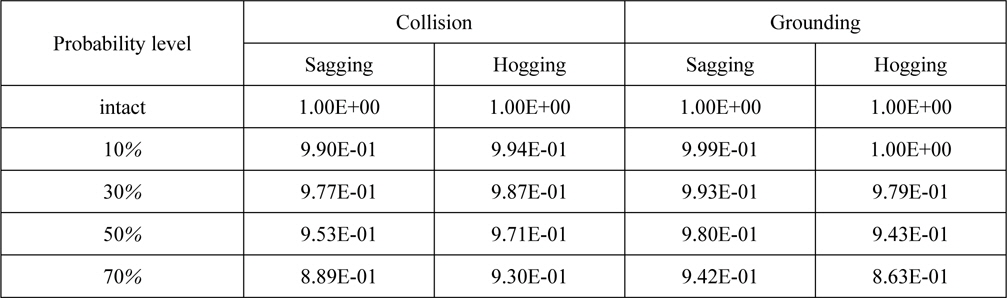
Minimum hull girder strengths of commercial vessels are generally found under sagging (MP = 0°) or hogging (MP = 180°) moment conditions. Fig. 7(a) and (b) present comparison of moment-curvature curves levels for sagging and hogging conditions, respectively, according to the probabilistic damage. The residual ultimate strengths normalized by intact ones are summarized in Table 3. For both cases of collision and grounding, the ultimate bending moment reduces as damage extent increases. For a section with collision-induced damages, reduction of the ultimate capacity for the sagging moment condition is more remarkable than that for the hogging moment condition. Meanwhile, ultimate strengths for grounding damage cases reduce more rapidly. As depicted in Fig. 6, a failure of bottom shell plating due to grounding may lead to a large shift-up of the NAP, which would consequently deteriorate resistance for an external hogging moment.
[Table 3] Comparison of ultimate residual strengths for sagging and hogging moment conditions.

Comparison of ultimate residual strengths for sagging and hogging moment conditions.
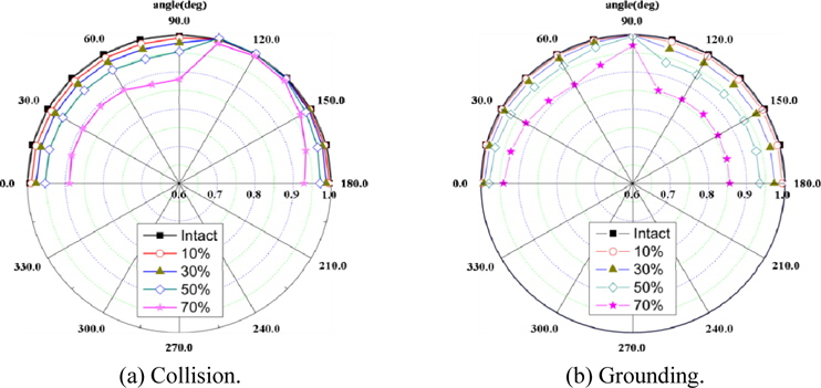
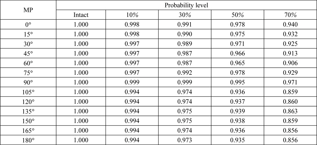
The residual ultimate strengths corresponding to MPs from 0° (sagging) to 180° (hogging) with 15° increments are assessed for one intact and four damaged conditions. A damage index, originally proposed by Wang et al. (2002), implies the residual ultimate strength normalized by intact one corresponding to each MP. Polar plots of damage indices are shown in Fig. 8(a) and (b) for collision and grounding damages, respectively. It is pretty reasonable to conclude from the data in Table 4 and Fig. 8(a) that minimum damage indices are found for the MP equal to 75°, because the failed structural units are located at the orthogonally farthest zone from the NAP and, thereby, loss of section modulus is most remarkable. On the other hand, smallest damage index is observed for the MP equal to 180° (sagging moment). As previously mentioned, in the case of grounding, loss of structural units in bottom shell structures reduces hogging resistance.
[Table 4] Damage index for collision damage.
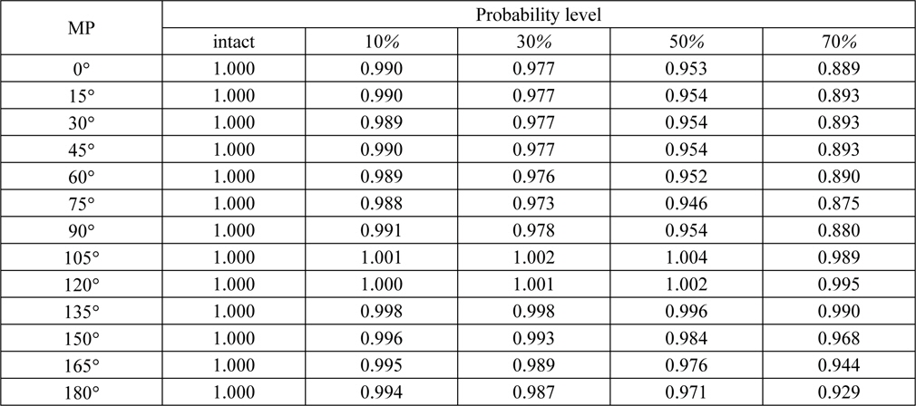
Damage index for collision damage.
[Table 5] Damage index for grounding damage.
Damage index for grounding damage.
>
Prediction of residual ultimate strength
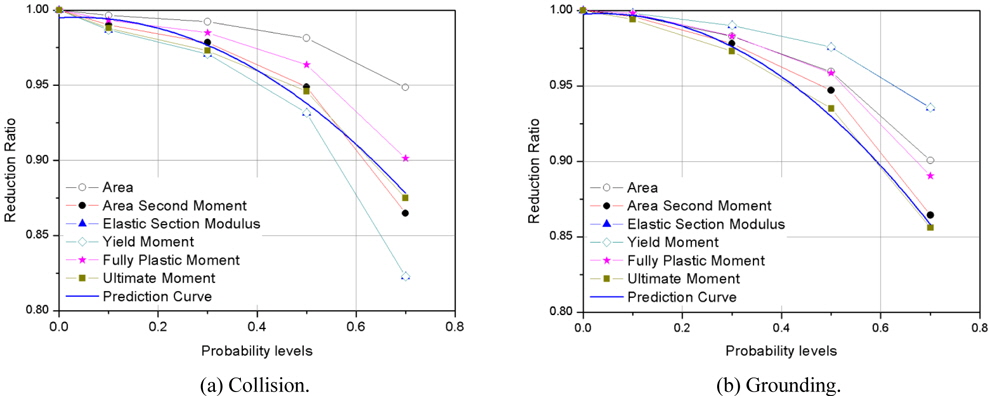
For two MPs of 75° and 180° showing critical reduction of ultimate strengths due to collision and grounding, reduction ratios of other section properties versus probability level reveal good clues for the prediction of residual ultimate strengths. Six reduction properties are compared each other: reduction ratios of area, second moment of area, elastic section modulus, yield moment, fully plastic moment, and ultimate moment. It should be noted that ultimate moment is derived based on moving neutral axis plane, while the others based on elastic neutral axis plane.
As shown in Figs. 9(a) and (b), the reduction curves of residual ultimate moment due to collision and grounding (symbol: ■) appear to best follow the reduction ratio curves of second moment of area. For the initial design purpose, one can obtain simple prediction from the reduction ratio curve of second moment of area (symbol: ●).
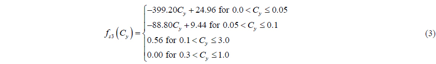
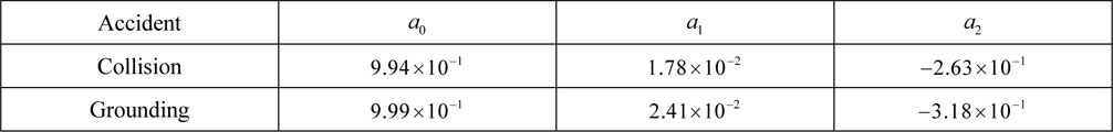
Polynomial-type linear regressions are analyzed for both reduction ratio curves of ultimate moments due to collision and grounding, respectively. The blue solid lines present regression curves in Fig. 9. Eq. (11) presents the general form of polynomials, where constants for collision and grounding are listed in Table 6. A covet needs to be noted that Eq. (11) and Table 6 should be used with some restrictions such as damage type, damage location, damage extent, vessel type and vessel size. The derived constants are based on analyses of a typical VLCC designed according to IACS (2010). For small-sized tankers and other types of vessels, another formulation or derivation of polynomial constants may be required.

[Table 6] Polynomial constants for residual ultimate strength prediction.

Polynomial constants for residual ultimate strength prediction.
In this paper, a new progressive collapse method is explained. This method was developed because a new convergence criterion should be required to obtain the residual hull girder ultimate strength for asymmetrically-damaged vessels. For a VLCC, the new method is applied to obtain the residual longitudinal strengths of collision- and grounding-induced damaged ships where probabilistic extents of damage are determined based on IMO Guidelines (2003). An intact condition and four damaged conditions with 10%, 30%, 50%, and 70% probability levels are taken into account for both collision and grounding accidents. The residual ultimate strength analyses are carried out increasing the moment planes by 15°.
Considering upright condition (zero MP), failure of bottom shell plating due to grounding may cause a large shift-up of the NAP, hence it largely deteriorates hogging resistance. Meanwhile collision-induced damage reduces sagging resistance more than hogging resistance.
Considering general healing condition, maximum compression is concentrated on the zone in way of side shell sheer strakes which are the farthest from the NAP for the MP equal to 75° with collision damage, hence the minimum residual ultimate strength is found at this MP. Failure in structural units in the bottom shell structures reduces hogging resistance, and therefore the hogging moment results in a large reduction in grounding-induced damage.
From a comparison of reduction ratios of the residual ultimate strength with one of the other sectional properties, this paper suggests that reduction of ultimate strengths is of similar level of reduction of second moment of area for both cases of collision and grounding. It implies that one can predict the residual ultimate strength of a VLCC from reduction second moment of area by using proposed polynomial equation with proposed constants.
This tendency should be verified for various types and sizes of vessels as a future work. Further study on damage sizes and locations are to be carried out based on experiments and simulations. For the damage size predictions by numerical simulations, study on failure criteria will be necessarily preceded. This paper adopts shortening curves based on CSR formulas which contain no effect of external and liquid cargo pressure, therefore effect of shortening curves on hull girder can be excellent topic for ultimate strength study area.